


RWB 6104 BNX R02 Page 5
Inspect/Prepare Installation Site
Combustion Air Supply Information
See NFPA Standard 31 for complete details.
Appliances located in confi ned spaces: All
confi ned spaces should have two (2) permanent
openings; one near the top of the enclosure and
one near the bottom of the enclosure. Each open-
ing must have a free area of not less than one (1)
square inch per 1,000 BTU’s per hour of the total
input rating of all appliances within the enclosure.
The openings should have free access to the build-
ing interior, which should have adequate infi ltration
from the outside.
Exhaust fans and other air-using devices: Size
air openings large enough to supply all air-using
devices in addition to the minimum size required
for combustion air. If there is any possibility of the
equipment room developing a negative pressure
due to exhaust fans, clothes dryers, etc., either pipe
combustion air directly to the burner or provide a
sealed enclosure for the burner and supply it with
its own combustion air supply.
Direct/Sidewall Venting Application
•
•
For direct vent installations, follow instructions pro-
vided with appliance and direct vent system. Out-
side combustion air is required for direct venting.
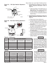
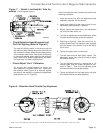
When installing an NX outside air adapter (Beckett
Part Number 1014U), refer to the instruction sheet
supplied with the adapter. This kit allows combus-
tion air to be piped directly to the burner. The NX
outside air adapter kit may also be used for chim-
ney vent applications that require outside combus-
tion air.
Fuel Line Installation •
Never use Tefl on tape on fuel oil fi ttings.
Tape fragments can lodge in fuel line components
and fuel unit, damaging the equipment and pre-
venting proper operation.
Use oil-resistant pipe sealant compounds.
•
•
•
Damage to the pump could cause impaired burn-
er operation, oil leakage and appliance soot-up.
Do Not Use Tefl on Tape
!
!
CAUTION
NOTICE
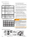
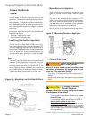
Connect Outside Air Duct
to NX Adapter
The outside air adapter must be installed by strictly
following the kit installation instructions.
DO NOT attempt to install outside air piping without
using the outside air adapter and instructions pro-
vided.
Abundant fresh air is required for proper combus-
tion.
•
•
•
Failure to install adapter properly
could result in impaired combustion,
appliance soot-up, puffback of smoke,
and fi re or asphyxiation hazards.
WARNING
!
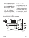
Route the fuel line through the opening in the bottom
of the burner cover. Continuous lengths of heavy
wall copper tubing are recommended. Always use
fl are fi ttings. Never use compression fi ttings.
Always install fi ttings in accessible locations. To
avoid vibration noise, fuel lines should not run
against the appliance or ceiling joists.
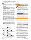
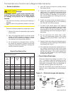
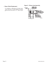
Fuel Line Valves and Filter
Install two high quality fusible-handle design shutoff
valves in accessible locations on the oil supply line
to comply with the NFPA31 Standard. Locate one
close to the tank and the other close to the burner,
upstream of the fi lter.
Install a generous capacity fi lter inside the building
between the fuel tank shutoff valve and the burner,
locating both the fi lter and the valve close to the
burner for ease of servicing. Filter should be rated
for 50 microns or less.
To further protect the fuel supply system and re-
duce nozzle orifi ce plugging with fi ring rates below
0.75 gph, a dual fi ltration system can be installed.
This typically consists of a 50 micron primary fi lter,
located near the fuel tank and a secondary fi lter rat-
ed for at least 10 microns located near the burner.
•