


RWB 6104 BNX R02 Page 15
For best performance specify genuine Beckett replacement parts
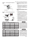
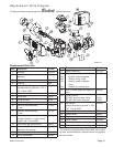
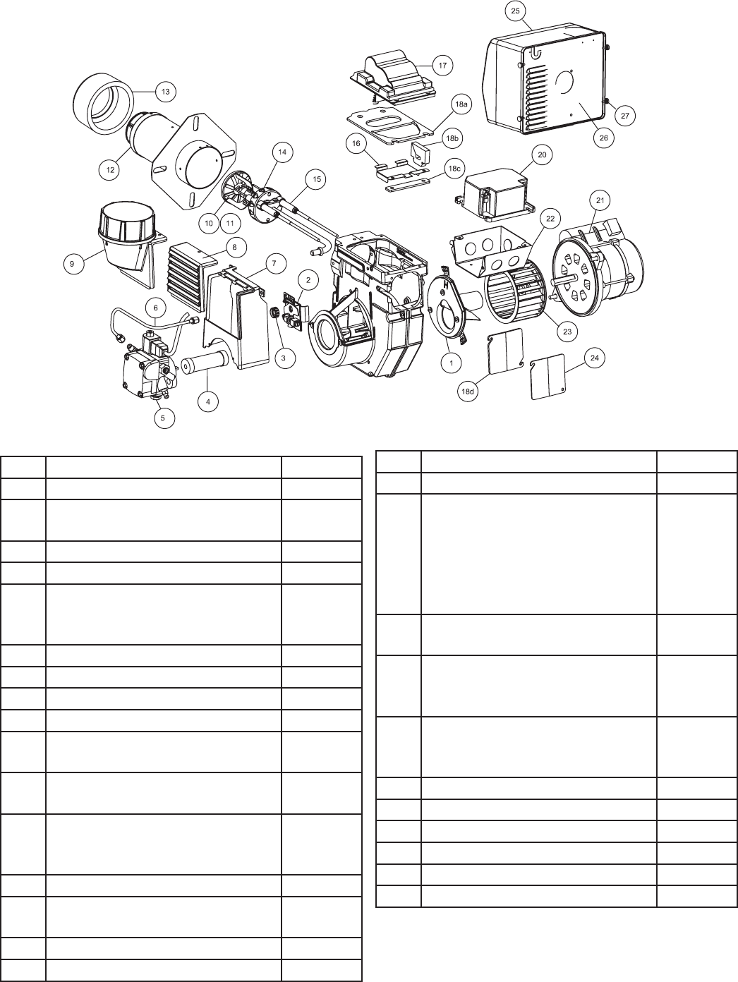
Replacement Parts Diagram
SK967101
Item Description Part No.
1 Air guide 101101U
2 Head/Air adjustment mechanism
assembly
51794U
3 Splined nut 3666
4 Coupling 2454
5 CleanCut Fuel Pump,
(Includes Mounting Screws ¼ -20 x
7/8” - Part # 4189)
2184404U
6 Connector tube assembly, 11” 51127
7 Inlet air box 1010U
8 Inlet air louvers 1013U
9 Inlet Air Adapter, Outside air kit 1014U
10 Retention head assembly,
6 -slot *
51785U
11 Retention head assembly,
9 -slot *
51815U
12 Air tube combination,
(Includes Screws, air tube mount-
ing #8 x 3/8 - Part # 4396)
Specify
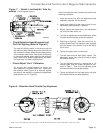
13 Heat Shield (per specifi cation) Specify
14 Nozzle Line Electrode and Head
Assembly, with window
Specify
15 Electrode insulator kit 51811U
16 Spring, igniter prop 32058U
Item Description Part No.
17 Igniter, electronic 51771U
18
18a
18b
18c
18d
Gasket, Igniter Kit
Gasket, igniter baseplate
Gasket, wiring hinge
Gasket, igniter baseplate
hinge
Gasket, rear access door
51942U
19 Low Fire Rate Baffl e (per specifi ca-
tion)
32229U
20 Primary control
R7184P Valve-on/Motor Delay
R7184P With Alarm Contacts
7457U
7458U
21 PSC Motor,
(Requires Mounting screws ¼ -20 x
7/8” - Part # 4189)
21805U
22 Electrical box 5770
23 Blower wheel 2999U
24 Door, rear access 32119U
25 Cover, Burner 51812U
26 Mounting Plate, Burner Cover 32103U
27 Thumbscrews, Cover mounting 21899U
Replacement Parts List
* For retention head assemblies that do NOT have a sight-
ing hole, contact Beckett’s customer service for appropri-
ate part number.