


Page 4 RWB 6104 BNX R02
General Specifi cations
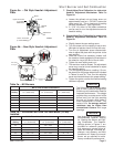
Table 1 – Burner Specifi cations
Capacity Firing rate: - 0.40 – 1.75 GPH
Input: Min. - 56,000 Btu
Max - 245,000 Btu
Certifi cation/
Approvals
UL certifi ed to comply with ANSI/UL296 &
tested to CSA B140.0
Fuels U. S No. 1 or No. 2 heating oil only (ASTM
D396)
Canada No. 1 stove oil or No. 2 furnace oil
only
Electrical Power supply - 120 volts AC, 60 Hz, single
phase
Operating load - 5.8 Amps max
Motor - 1/7 hp, 3450 rpm, NEMA 48M
frame PSC rotation CCW when
facing shaft end
Ignition - Continuous duty solid-state igniter
Fuel pump Outlet pressure - Note 1
Air tube ATC code - See Table 2
Dimensions
(with cover)
Height (maximum) - 12-1/2 inches
Width (maximum) - 15 inches
Depth - 9-1/4 inches
Air tube diameter - 3-1/4 inches
*Note 1. See appliance manufacturer’s burner specifi cations for
recommended outlet pressure.
Table 2 – Air Tube Combinations (ATC)
Firing rate
(gph)
Head ATC codes for usable air tube
lengths:
(min-max) 5” 7” 9”
0.40-1.00 9-Slot NX50LG NX70LG NX90LG
0.40-1.00 6-Slot NX50LH NX50LH NX90LH
0.40-1.35 9-Slot NX50LB NX70LB NX90LB
0.40-1.35 6-Slot NX50LC NX70LC NX90LC
1.10-1.75 9-Slot NX50LD NX70LD NX90LD
1.10-1.75 6-Slot NX50LF NX70LF NX90LF
•
Notice Special Requirements
For recommended installation practice in Canada,
refer to the latest version of CSA Standard B139 &
B140.
Concealed damage — If you discover damage to
the burner or controls during unpacking, notify the
carrier at once and fi le the appropriate claim.
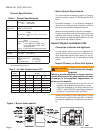
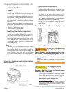
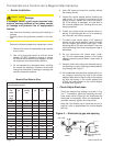
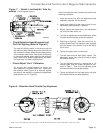
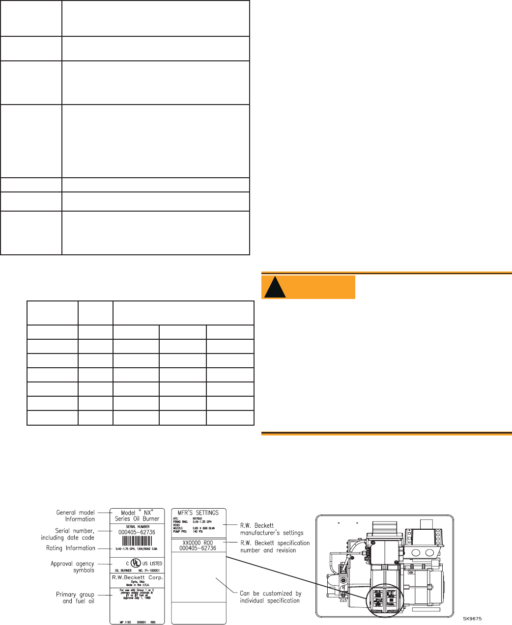
When contacting Beckett for service information —
Please record the burner serial number (and have
available when calling or writing). You will fi nd the
serial number on the silver label located on the left
rear of the burner. Refer to Figure 1.
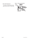
Inspect/Prepare Installation Site
Clearances to Burner and Appliance
Provide space around burner and appliance for
ease of service and maintenance. Check the mini-
mum clearances against those shown by the ap-
pliance manufacturer and by applicable building
codes.
Inspect Chimney or Direct Vent System
•
•
•
Figure 1. Burner label location
General Information
Inspect the chimney or vent. Make sure it is prop-
erly sized and in good working condition. Follow the
instructions supplied by the appliance manufactur-
er.
The burner cannot properly burn the fuel if it is not
supplied with a reliable combustion air source.
Follow the guidelines in the latest editions of the
NFPA 31 and CSA-B139 regarding providing ad-
equate air for combustion and ventilation.
•
•
Failure to provide adequate air supply could se-
riously affect the burner performance and result
in damage to the equipment, asphyxiation, ex-
plosion or fi re hazards.
Adequate Combustion
and Ventilation Air Supply
Required
WARNING
!