


RWB 6104 BNX R02 Page 7
The burner is supplied with either a one-stage
pump or a two-stage pump based on the oil supply
system requirements. Consult the instructions pro-
vided with the pump for installation specifi cations.
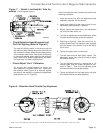
When installing a one-pipe system, connect the
inlet line to the pump inlet. The fuel pump may be
installed with gravity feed or lift. The maximum al-
lowable lift for a single pipe installation is 8 ft.
When installing a two-pipe system, remove the
1/16” pipe by-pass plug from plastic bag attached
to fuel unit. Remove 1/4” plug from return port.
Insert and tighten the by-pass plug. Attach return
and inlet lines. The return line should terminate ap-
proximately 3 to 4” above supply line inlet. Failure
to do this may introduce air into the system and
could result in loss of prime.
Start the Burner and Set Combustion
Wiring Connections Diagram
Refer to the appliance manufacturer’s wiring dia-
gram prior to connecting the burner wiring. All wir-
ing must be in accordance with the latest revision of
National Electric Code NFPA 70 and all local codes
and regulations.
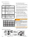
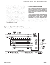
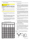
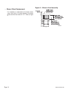
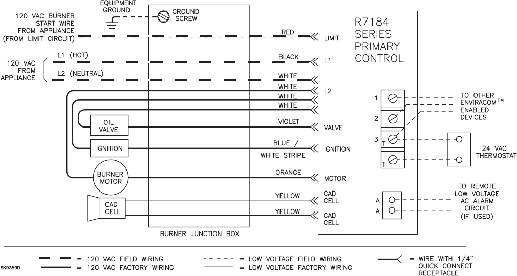
The R7184 primary control with valve-on delay and
burner motor-off delay, shown in Figure 4, requires
a constant 120 volt AC power source supplied to
the black wire on the control. (Refer to the appli-
ance manufacturer’s instructions.) The red wire
goes to the appliance limit circuit. Please note that
other control manufacturers may use different wire
colors for power and limit connections.
•
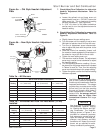
Figure 4a. – Typical Burner Control Wiring
Refer to the appliance manufacturer’s wiring diagram for actual specifi cations.