Page 8 RWB 6104 BNX R02
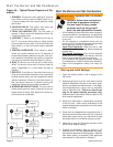
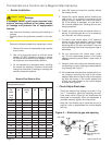
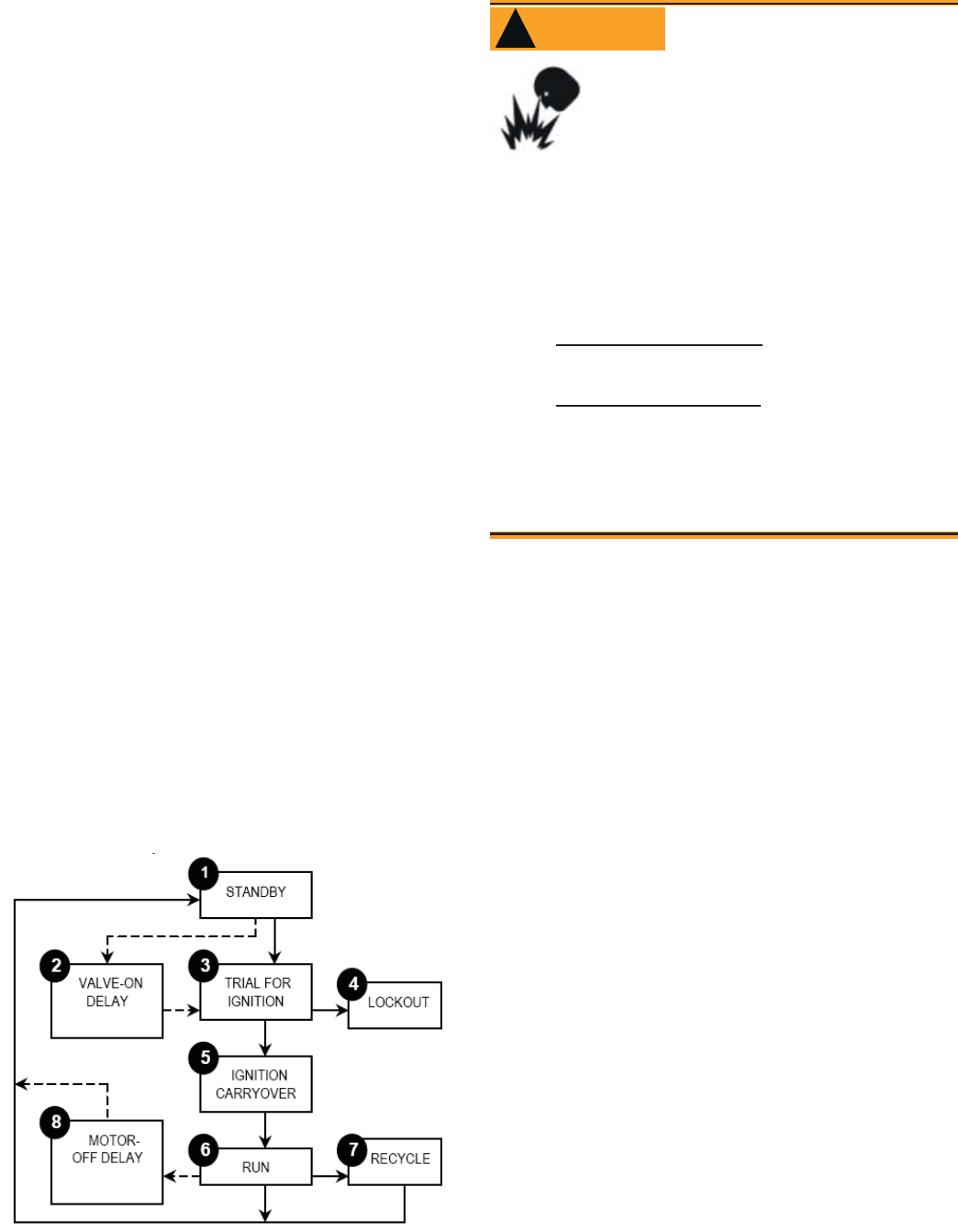
1. STANDBY. The burner is idle, waiting for a call for
heat. When a call for heat is initiated, there is a 3-
10 second delay while the control performs a safe
start check.
2. VALVE-ON DELAY. The ignition and motor are
turned on for a 15 second valve-on delay.
3. TRIAL FOR IGNITION (TFI). The fuel valve is
opened. A fl ame should be established within the
15 second lockout time.
4. LOCKOUT. If fl ame is not sensed by the end of
the TFI, the control shuts down on safety lockout
and must be manually reset. If the control locks out
three times in a row, the control enters restricted
lockout.
5. IGNITION CARRYOVER. Once fl ame is estab-
lished, the ignition remains on for 10 seconds to
ensure fl ame stability before turning off. If the con-
trol is wired for intermittent duty ignition, the ignition
unit stays on the entire time the motor is running.
6. RUN. The burner runs until the call for heat is sat-
isfi ed. The burner is then sent to burner motor off
delay, if applicable, or it is shut down and sent to
standby.
7. RECYCLE. If the fl ame is lost while the burner is
fi ring, the control shuts down the burner, enters a 60
second recycle delay, and then repeats the above
ignition sequence. If fl ame is lost three times in a
row, the control locks out to prevent cycling with
repetitious fl ame loss due to poor combustion.
8. BURNER MOTOR-OFF DELAY. The fuel valve is
closed and the burner motor is kept on for the se-
lected motor-off delay time before the control re-
turns the burner to standby.
61351
Start the Burner and Set Combustion
Start the Burner and Set Combustion
Do not attempt to start the burner when excess oil
has accumulated in the appliance, the appliance
is full of vapor, or when the combustion chamber
is very hot.
Do not attempt to re-establish fl ame with the
burner running if the fl ame becomes extinguished
during start-up, venting, or adjustment.
Vapor-Filled Appliance: Allow the unit to cool
off and all vapors to dissipate before attempting
another start.
Oil-Flooded Appliance: Shut off the electrical
power and the oil supply to the burner and then
clear all accumulated oil before continuing.
If the condition still appears unsafe, contact the
Fire Department. Carefully follow their directions.
Keep a fi re extinguisher nearby and ready for
use.
•
•
•
•
•
•
Failure to follow these instructions
could lead to equipment malfunc-
tion and result in heavy smoke
emission, soot-up, hot gas puff-
back, fi re and asphyxiation hazards.
Explosion and Fire Hazard
WARNING
!
Start-up and Initial Settings
Open the shutoff valves in the oil supply line to
the burner.
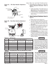
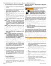
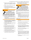
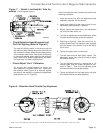
Referencing Figure 5a or 5b, verify and/or set the
Head/Air Adjustment Pointer to the value speci-
fi ed by the Appliance Manufacturer. If the Appli-
ance Manufacturer’s values are not available,
refer to Table 3a or 3b. (This is an initial air set-
ting for the pump bleeding procedure only.)
Calibrated test instruments must be used for the
fi nal head/air adjustment.
Adjust the thermostat or temperature controller
to call for heat. (Note: return controller(s) to the
original settings upon completion of burner instal-
lation or service.)
Close the line voltage switch to start the burner. If
the burner does not start within the 3 to 10 second
safety start check timing, you may have to reset
the safety switch on the burner primary control.
Bleed the air from the fuel pump as soon as the
burner motor begins rotating.
Prepare for combustion tests by drilling a
1/4
”
sampling hole in the fl ue pipe between the appli-
ance and the barometric draft regulator. Seal this
hole when testing is complete. (See appliance
manufacturer’s instructions for location.)
•
1.
2.
3.
4.
5.
6.
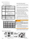
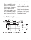
Figure 4b. – Typical Burner Sequence of Op-
eration


