


RWB 6104 BNX R02 Page 11
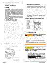
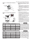
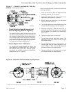
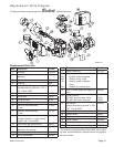
Removing Nozzle Line for Service (Refer-
ence the Replacement Parts Diagram.)
•
Trained Service Technician’s Regular Maintenance
Before proceeding, turn off the main power switch
to the burner.
Remove the burner cover by loosening the four
thumb screws (two on each side of burner).
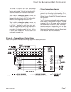
Disconnect the copper connector tube assembly
from the nozzle line bulkhead fi tting.
Loosen the two screws securing the igniter re-
taining clips and rotate both clips to release the
igniter baseplate. The igniter should pop up and
be supported by the prop spring.
Loosen the two screws securing the rear door.
Swing the door to the right and down.
Loosen the splined nut.
Remove the nozzle line electrode and head as-
sembly from the burner by drawing it straight
back and out the rear door opening. The adjust-
ment mechanism is still attached. Be careful not
to damage the electrodes or insulators while han-
dling.
To replace the nozzle assembly, reverse the
above procedure.
1.
2.
3.
4.
5.
6.
7.
8.
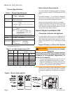
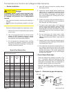
Use only nozzles having the brand, fl ow rate (gph), spray
angle and pattern specifi ed by the appliance manufactur-
er or Beckett Residential Burner OEM Spec Guide, Part
#6711.
Follow the appliance manufacturer’s specifi cations for the
required pump outlet pressure for the nozzle, since this
affects the fl ow rate.
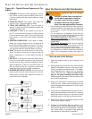
Nozzle manufacturers calibrate nozzle fl ow rates
at 100 psig.
This burner utilizes pressures higher than 100
psig, so the actual nozzle fl ow rate will be greater
than the gph stamped on the nozzle body. (Exam-
ple: A 1.00 gph nozzle @ 140 psig = 1.18 gph)
For typical nozzle fl ow rates at various pressures see ac-
companying chart.
•
•
Incorrect nozzles and fl ow rates
could result in impaired combus-
tion, under-fi ring, over-fi ring, soot-
ing, puff-back of hot gases, smoke
WARNING
!
Correct Nozzle and Flow
Rate Required
and potential fi re or asphyxiation hazards.
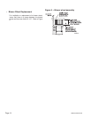
Make sure Low Firing Rate Baffle is in place if
required for the burner application. Omitting the
baffle can result in unacceptable burner combus-
tion.
Inspect all gaskets. Replace any that are dam-
aged or would fail to seal adequately.
Clean the blower wheel, air inlet, air guide, reten-
tion head, throttle cup and throttle ring of any lint
or foreign material.
Use a clean soft cloth and degreaser, on an an-
nual basis, to remove any build-up or dark stains
from the windows.
If damaged, replace the nozzle line assembly with
an assembly that has a windowed throttle cup.
•
•
If a window is punctured, signifi -
cantly scratched or removed from
the throttle cup, the burner perfor-
Do Not Puncture, Scratch,
or Remove Flame Sight-
ing Windows
mance could be impaired, resulting in safety
lockout, appliance soot-up, equipment damage,
hot gas puff-back and asphyxiation hazard.
WARNING
!
Use a clean soft cloth with a degreaser to
clean any accumulated soot or oil stains from
the throttle cup sight windows.
Check motor current. The amp draw should not
exceed the nameplate rating.
Check all wiring for secure connections or insula-
tion breaks.
Check the pump pressure and cutoff function.
Check primary control safety lockout timing.
Check ignition system for proper operation.
Inspect and clear the vent system and chimney of
any soot accumulation or other restriction.
Clean the appliance thoroughly according to the
manufacturer’s recommendations.
Check the burner performance. Refer to the sec-
tion “Set combustion with test instruments”.
It is good practice to keep a record of the service
performed and the combustion test results.