


Page 12 RWB 6104 BNX R02
Nozzle Installation •
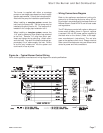
Nozzle fl ow rate U. S. gallons per hour of No. 2 fuel oil when
pump pressure (psig) is:
Nozzle
size
(rated
at 100
psig)
125
psi
140 psi
(factory
std.)
150
psi
175
psi
200
psi
0.40 0.45 0.47 0.49 0.53 0.56
0.50 0.56 0.59 0.61 0.66 0.71
0.60 0.67 0.71 0.74 0.79 0.85
0.65 0.73 0.77 0.80 0.86 0.92
0.75 0.84 0.89 0.92 0.99 1.06
0.85 0.95 1.01 1.04 1.13 1.20
0.90 1.01 1.07 1.10 1.19 1.27
1.00 1.12 1.18 1.23 1.32 1.41
1.10 1.23 1.30 1.35 1.46 1.56
1.20 1.34 1.42 1.47 1.59 1.70
1.25 1.39 1.48 1.53 1.65 1.77
1.35 1.51 1.60 1.65 1.79 -
1.50 1.68 1.77 1.84 - -
1.65 1.84 - - - -
1.75 -----
Nozzle Flow Rate by Size
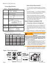
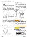
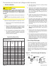
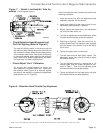
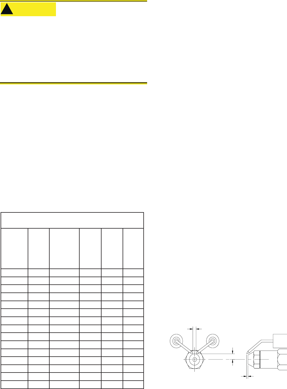
Figure 6. – Electrode tip gap and spacing
5/32” GAP
1/4” above
nozzle center
3/32” Nozzle-to-tip
Spacing
SK9664
Trained Service Technician’s Regular Maintenance
Use a 5/8” open-end wrench to carefully remove
the existing nozzle.
Inspect the nozzle adapter before installing the
new nozzle. If it is grooved or scratched on the
sealing surface, replace the nozzle line assem-
bly. If the surface is damaged, oil could leak at
the nozzle to adapter joint, causing serious com-
bustion problems.
Protect the nozzle orifi ce and strainer when in-
stalling. If the orifi ce gets dirt in it or is scratched,
the nozzle will not function properly.
To install a new nozzle, place a 3/4” open-end
wrench on the nozzle adapter. Insert the nozzle
into the adapter and secure fi nger tight. Finish
tightening with a 5/8” open-end wrench. Use care
to avoid bending the burner head support legs or
electrodes.
Do not over-torque the nozzle when install-
ing. This will cause deep grooves in the nozzle
adapter, preventing a seal when a new nozzle is
installed.
Carefully check and realign the electrode tips af-
ter replacing a nozzle, ensuring the electrode set-
tings comply with Figure 7.
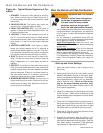
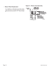
If the head was removed when replacing the noz-
zle, carefully reconnect the head to the nozzle
adapter. Make sure to align the key in the support
leg with the keyway in the nozzle adapter and
to butt the head support to the nozzle adapter
shoulder, see Figure 8.
Check/Adjust Electrodes
Check the electrode tip settings, as shown in Fig-
ure 7. If necessary, adjust by loosening the elec-
trode clamp screw (Figure 8) and slide/rotate the
electrodes as necessary. When the adjustment is
complete, securely tighten the clamp screw.
Note that if the throttle cup is moved be sure to re-
position it with no gap between the nozzle adapter
and hub.
4.
5.
6.
7.
8.
9.
10.
•
Perform the following steps when replacing a nozzle.
Remove the nozzle line assembly to gain access
to the nozzle.
Use a 3/4” open-end wrench to hold the nozzle
adapter. DO NOT attempt to remove or replace
the nozzle without securing the adapter, as noz-
zle alignment could be seriously affected.
Do not squeeze the electrodes when handling
the nozzle line assembly. Excessive force could
change the electrode tip settings or damage the
ceramic electrode insulators.
1.
2.
3.
Use care when handling, removing and installing oil
nozzles.
Carefully follow the guidelines provided in this sec-
tion.
•
•
A damaged nozzle could cause impaired com-
bustion, sooting, puffback of hot gases, smoke,
oil leakage and potential fi re or asphyxiation
hazards.
Protect Nozzle from
Damage
!
!
CAUTION