


RWB 6104 BNX R02 Page 13
Trained Service Technician’s Regular Maintenance
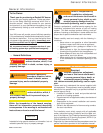
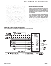
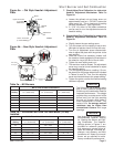
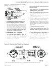
Figure 7. – Nozzle Line/Head/Air Tube As-
sembly
(Low fi ring rate shown.)
Retention Head
Retention Head
Head Support Legs
Head Support Legs
Electrode Tips
Electrode Tips
Electrode Clamp
Electrode Clamp
Electrode Bracket
Electrode Bracket
Electrode Insulator
Electrode Insulator
Electrode Extension Rods
Electrode Extension Rods
NozzleAdapter
NozzleAdapter
Nozzle
Nozzle
Stops in Retention Ring
Stops in Retention Ring
Retention Ring
Retention Ring
Throttle Ring
Throttle Ring
Throttle Cup
Throttle Cup
Nozzle Line
Nozzle Line
Bulkhead Fitting
Bulkhead Fitting
SK9666A
SK9666A
Throttle Cup Hub
Throttle Cup Hub
SK9666A
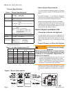
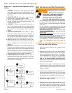
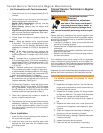
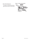
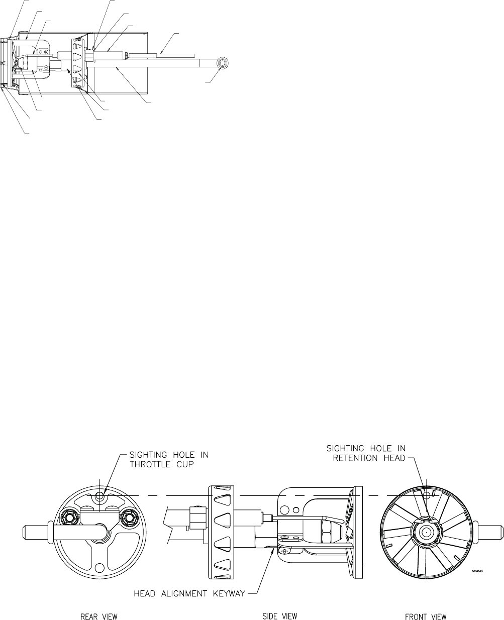
Figure 8 – Retention Head/Throttle Cup Alignment
Check Retention Head Alignment and
Cad Cell Sighting (Refer to Figure 8.)
The cad cell sighting holes in the throttle cup and
the retention head must be aligned to allow the cad
cell to detect the fl ame. Make sure the stamped key
in the retention head collar lines up with the keyway
in the nozzle adapter when mounting the retention
head. Note that in specifi c applications, the reten-
tion head may not have a sighting hole.
Check/Adjust “Zero” Calibration
On burners with factory-installed air tubes, the
zero calibration has been factory set. Make sure
the retention head (Figure 8) is securely against
the stops in the retention ring when the adjustment
plate pointer is at “0” (Figure 5).
•
•
If the zero calibration has not been set, perform the
following procedure:
Install the nozzle line, with the adjustment plate
assembly attached, into the burner.
Install and tighten the rear door to hold the air
adjustment plate assembly in position.
Slightly loosen the upper acorn nut, the splined
nut, and the lower acorn nut.
Turn the air adjustment screw clockwise to adjust
the plate with the pointer to the zero position.
Referring to Figure 8, slide the nozzle line as-
sembly forward until the retention head engages
the fi xed stops in the retention ring at the end of
the air tube.
Tighten the upper acorn nut securely.
The rear door must be kept tightly closed. The
adjustment screw may now be turned to adjust
the head/air setting.
Turn the adjusting screw to a setting that is 1/2
number lower than the proper set point as indi-
cated in Table 1. Then turn the adjusting screw
counterclockwise to the proper setting.
Tighten the splined nut and lower acorn nut after
the head/air setting has been adjusted.
1.
2.
3.
4.
5.
6.
7.
8.
9.
*