


9
CG10 Burner Manual
Mount the burner to the appliance. The burner specifi ed
for packaged equipment will have a fl ange welded for the
required insertion. Follow the appliance manufacturer’s
instructions for mounting.
In the absence of instructions, or for retrofi ts, make sure
that the air tube insertion dimension, measured along
the side of the air tube from the welded fl ange to the end
of burner air tube, is correct.
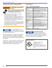
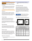
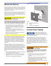
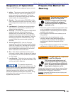
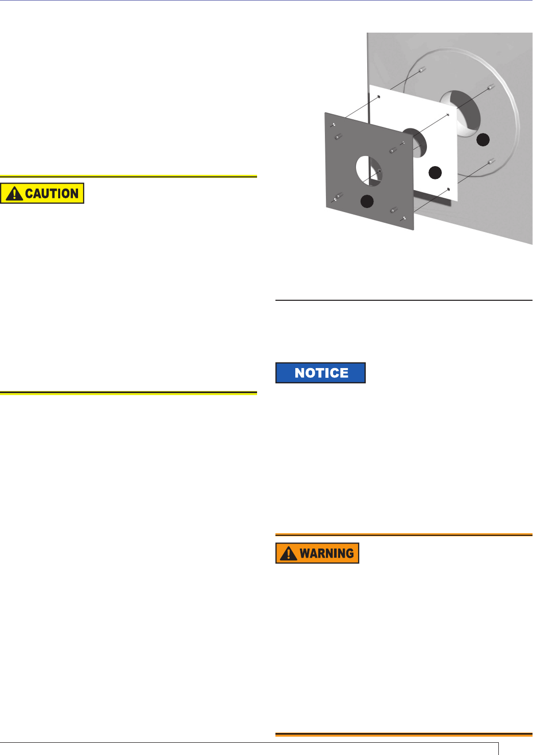
Figure 6. Custom Mounting Plate
All gas piping installation must
comply with the latest edition of
the National Fuel Gas Code ANSI Z223.1 (NFPA 54) and
other applicable local codes.
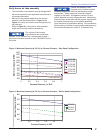
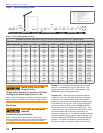
The gas supply system must be sized to deliver at
least the minimum required pressure to the gas train
inlet. Contact your local gas utility for verifi cation of
gas pressures, allowable pressure drops, and any local
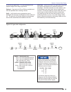
piping code requirements. Refer to Figure 7 for an
illustration of a gas piping layout and refer to Table 1 for
pipe sizing.
If this dimension cannot be achieved, protect the end
of the air tube by installing a suitable ceramic refractory
material such as a refractory mill board capable of
withstanding at least 2300°F. The entry hole diameter
in the appliance should be 1” larger than the air tube
to facilitate ease of installation and provide adequate
protection.
Referring to Figure 6, if the front plate opening (C) in
the boiler is larger than the burner fl ange bolt circle, then
a custom mounting plate (A) of at least 1/4” thickness
must be used with a suitable high-temperature refractory
material anchored on the fi re-side. A suitable high-
temperature gasket (B) must be used for an effective
seal.
Attach the plate and gasket to the boiler and tighten
the mounting nuts or bolts securely.
Verify that the air tube is ¼” back from fl ush (see
Figure 2), and there is nothing blocking the fl ame
zone that could cause fl ame impingement.
○
○
Mount the Burner
Connect Gas Piping
A
B
C
Key:
A Burner mouning fl ange
B Gasket
C Appliance mounting plate
Section: Mount the Burner & Connect Gas Piping
Protect the Air Tube from
Overheating
Overheating could cause damage to the air tube and
other combustion components leading to equipment
malfunction and impaired combustion performance.
The end of the air tube must not extend into the
combustion chamber unprotected unless it has
been factory-tested and specifi ed by the appliance
manufacturer.
The end of the air tube should be set back ¼”
from fl ush with the refractory inside wall to prevent
damage from overheating.
Refer to the instructions outlined in this section for
methods of additional protection.
y
y
y
Do Not Use Tefl on Tape on
Gas Piping
Damage to gas valve cutoff seals and valve bodies
could cause gas leaks and result in asphyxiation,
explosion or fi re.
Pieces of tape can be cut loose during installation
and lodge in gas valves causing cutoff seal
problems.
Tefl on tape ‘lubricates’ pipe threads, allowing iron
pipes to penetrate too deeply into aluminum valve
bodies causing distortion and leakage.
Use only pipe sealant compounds that are resistant
to the gas being used.
y
y
y