


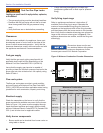

14
Start-up checklist
Verify the following before attempting to start
the burner:
1. General
Carefully read and become familiar with the CG10
Manual, Flame Safeguard Control Instructions,
sequence of operation, pertinent wiring diagrams,
gas system layout, insurance requirements,
other controls and valve literature pertinent to the
installation.
Follow the appliance manufacturer’s start-up
procedures (when available).
Inspect the combustion air supply and exhaust
venting and verify that they are free of obstructions
and installed and sized in accordance with all
applicable codes.
Notify appropriate personnel to schedule start-up
(gas utility, owner, operators, subcontractors, etc.).
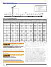
2. Gas Supply Piping
Insure that the gas piping is properly sized and has
been inspected by the gas utility, leak tested at all
joints, and purged.
To protect the gas train and controls, insure that a
drip leg or dirt pocket has been properly installed.
Insure that the fuel gas being supplied is compatible
with the burner specifi cation and is available at the
correct regulated pressure. (See burner name plate
and specifi cation sheets).
Insure that the vent lines for the diaphragm valves
have been run to the outside and properly terminated.
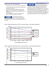
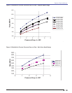
Use R.W. Beckett recommended maximum pipe
lengths for good lightoff (Figure 8).
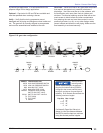
3. Electrical
Insure that all wiring has been completed and
complies with the National Electric Code NFPA 70
and local requirements.
Refer to Figure 1 and verify that the electrical supply
to the burner matches the voltage specifi cation on
the label.
4. Boiler or Appliance
Insure that the fl ue passages and combustion area
have been thoroughly cleaned and are in good
condition.
○
○
○
○
○
○
○
○
○
○
○
○
Set the breech damper to the required position for
system operation.
Fill the appliance with water (boilers).
Check all safety and operating controls for correct
application, installation, wiring, and operation.
Insure that the maximum capacity of the appliance is
compatible with the specifi ed burner input fi ring rate.
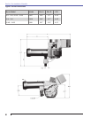
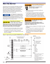
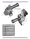
5. Burner - See Figure 10 for familiarization
Insure that the gas burner model and capacity meet
the requirements for the installation.
Insure that the gas train meets operating specifi cations,
all safety codes and insurance requirements.
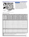
Refer to Table 2 and Figure 11 to insure that the
burner air shutter and band are positioned for initial
start-up preliminary settings.
Insure that the burner is securely mounted in the
appliance with the pressure fi ring plate and all gaskets
in place for pressurized chamber applications.
For propane-fi ring burners, insure that the propane
restrictor has been correctly selected for your burner
model (see Table 3) and properly installed (see
Propane Restrictor Installation instructions).
Before operating insure that all protective cover
plates, enclosures and guards are in place and
securely fastened.
When available, refer to the appliance
manufacturer’s instructions and install the burner
accordingly.
6. Test instruments
The following calibrated test equipment is required
to properly install the appliance. Whether these are
included in one kit or are individual test components,
they should be calibrated and in good working order.
A combustion analyzer capable of measuring
oxygen (or carbon dioxide), carbon monoxide, stack
temperature, ambient temperature, and appliance
effi ciency.
Electrical multi-meter capable of measuring voltage,
ohms, amps, and DC micro-ammeter for measuring
the fl ame signal. These could be included in one
meter or separate meters, but should be calibrated
and accurate.
Calibrated manometers and gauges capable of
measuring all pressure ranges in the gas supply and
appliance draft. This could typically range from a
few psi to 0.01” W. C.
○
○
○
○
○
○
○
○
○
○
○
○
○
○
○
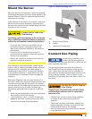
Section: Prepare the Burner for Start-up