


7
CG10 Burner Manual
400
500
600
700
800
900
1000
1100
1200
1300
1400
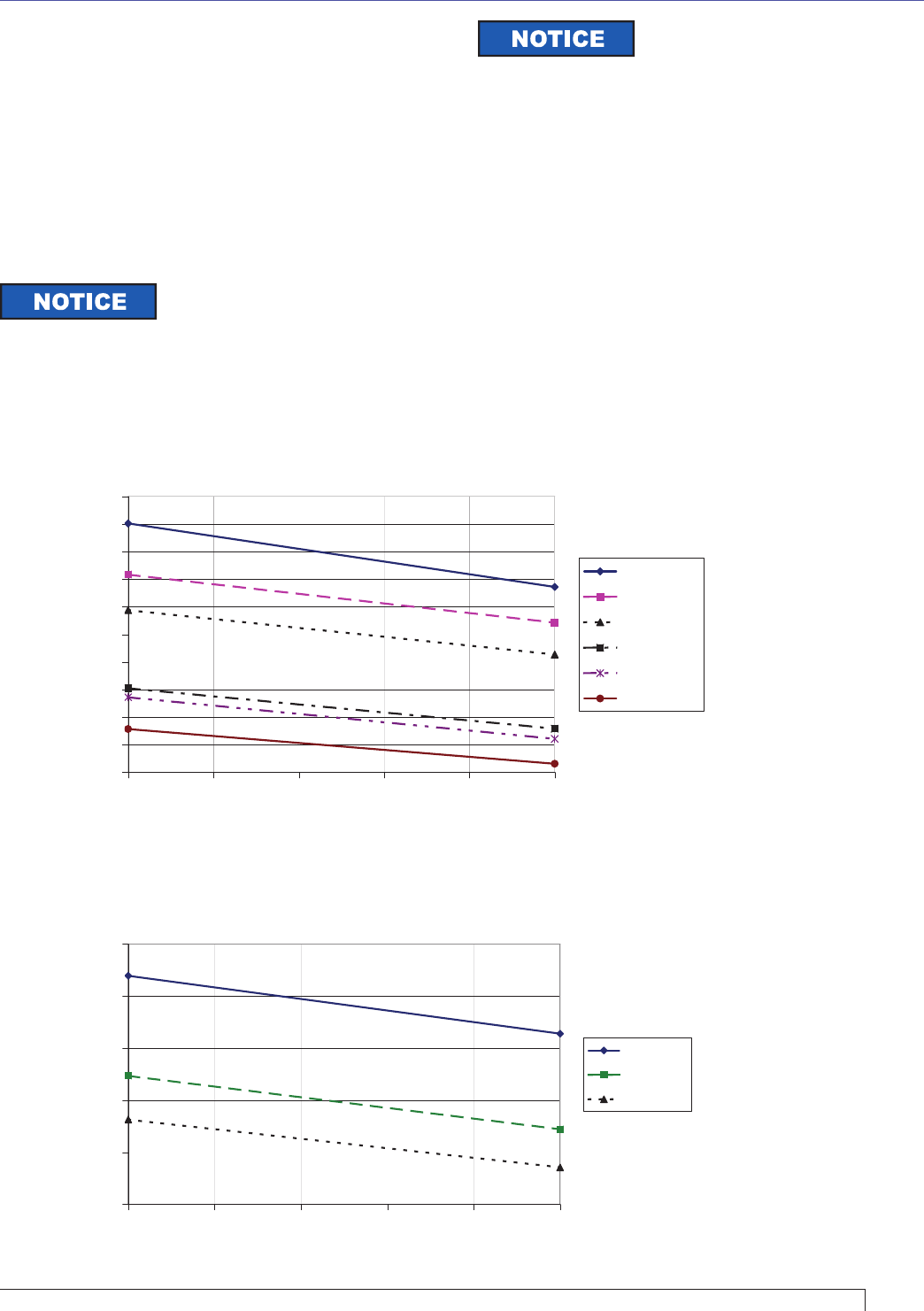
0 0.2 0.4 0.6 0.8 1
Furnace Pressure, In. W.C.
Maximum Capacity, MBH
CG10.6S
CG10.5S
CG10.4S
CG10.3S
CG10.2S
CG10.1S
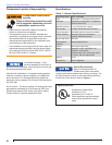
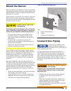
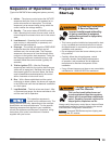
Verify burner air tube assembly
The information in this section may be disregarded if
the burner supplied by the appliance manufacturer is
a matched component.
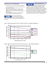
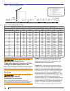
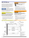
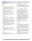
Maximum fi ring capacity depends on the furnace
pressure. Use the charts shown in Figure 3 and
Figure 4, to verify the correct burner confi guration for
the input rate.
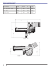
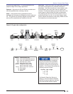
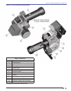
Refer to Figure 5 to verify the air tube assembly
length and mounting insertion dimensions.
○
○
○
Figure 3. Maximum Capacity (at 3% O
2
) vs Furnace Pressure - Step Spud Confi guration
Section: Pre-installation Checklist
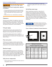
The volume of the furnace
also infl uences the combustion
process. R. W. Beckett Corp. recommends at least 1
cubic foot of furnace volume for each 150,000 BTU/Hr of
fi ring rate.
Flames are shaped by their
furnaces and by its fl ue locations.
Increased height and width can decrease the length
requirement. When shaping is too severe fl ames
impinge on the walls. Impingement causes CO and
carbon deposits and may damage the wall. Maintaining
these minimum dimensions should prevent impingement,
but smaller furnaces may be acceptable depending
upon the results of applications testing. We recommend
factory testing of all new burner/furnace combinations by
the furnace manufacturer and/or R. W. Beckett Corp.
300
400
500
600
700
800
0 0.2 0.4 0.6 0.8 1
Furnace Pressure, In. WC
Maximum Capacity, MBH
CG10.3
CG10.2
CG10.1
Figure 4. Maximum Capacity (at 3% O
2
) vs Furnace Pressure - Swirler Head Confi guration