


10
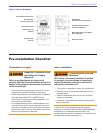
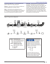
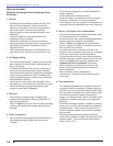
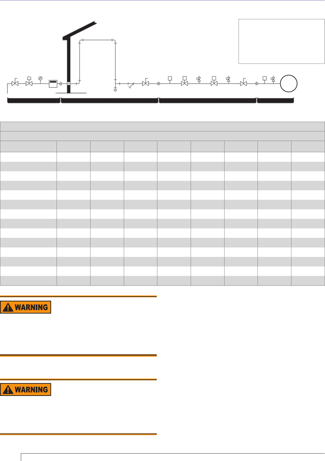
Figure 7. Typical Gas Piping Layout
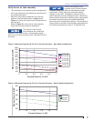
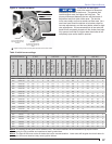
Schedule 40 metallic pipe with 0.50 psi or less inlet pressure and 0.30” W.C. pressure drop
Maximum capacity in cubic feet of gas per hour (CFH). Natural gas with 0.60 specifi c gravity. Pipe size (inches) IPS
Pipe Length (ft.) 0.75” 1.0” 1.25” 1.5” 2.0” 2.5” 3.0” 4.0”
10 278 520 1050 1600 3050 4800 8500 17500
20 190 350 730 1100 2100 3300 5900 12000
30 152 285 590 800 1650 2700 4700 9700
40 130 245 500 760 1450 2300 4100 8300
50 115 215 440 670 1270 2000 3600 7400
60 105 195 400 610 1150 1850 3250 6800
70 96 180 370 560 1050 1700 3000 6200
80 90 170 350 530 990 1600 2800 5800
90 84 160 320 490 930 1500 2600 5400
100 79 150 305 460 870 1400 2500 5100
125 72 130 275 410 780 1250 2200 4500
150 64 120 250 380 710 1130 2000 4100
175 59 110 225 350 650 1050 1850 3800
200 55 100 210 320 610 980 1700 3500
Table 1. Gas supply piping capacity
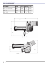
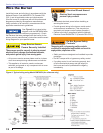
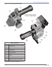
Gas Trains
Standard – An Underwriters Laboratories (UL) listed
gas train is standard for the CG10 gas burner. This
confi guration also meets CSD-1 requirements. See
Figure 8 for typical component layout.
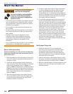
Propane (LP) – When the correct propane restrictor
is added to a burner’s gas pipe assembly it changes
the burner’s gas pressure drop so that the propane
pressure drop is equal to the natural gas pressure drop
of the same BTU fi ring rate. That is why the Manifold
to Furnace Pressure Drop curves of Figures 12 and
13 are correct for both propane and natural gas. That
is also why a gas train adjusted for the burner’s natural
gas requirements will be correctly adjusted for its
propane requirements. R. W. Beckett provides the same
pressure regulating safety shutoff valve in the gas train
(usually a Honeywell V4944B) for both natural gas and
propane. The valve is marked for natural gas due to
its primary usage in a pressure range normally used
LGPS
HGPS
S
(IF USED)
DRIP LEG
BURNER
METER
MSC
SSOV1
2PRV
MLTC
U
TC
U
TC
TC
U
PG
REGULATOR
ABBREV.
HGPS
LGPS
MSC
MLTC
PG
S
SSOV1
TC
U
2PRV
ITEM DESCRIPTION
HIGH GAS PRESSURE SWITCH
LOW GAS PRESSURE SWITCH
MAIN SHUTOFF COCK
MAIN LEAK TEST COCK
PRESSURE GAUGE
STRAINER
SAFETY SHUTOFF VALVE #1
TEST COCK
UNION
TWO POSITION REGULATING VALVE
GAS UTILITY PIPING
FACILITY PIPING
GAS TRAIN BURNER
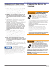
Section: Connect Gas Piping
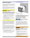
Install a Drip Leg in Gas
Supply Piping
Foreign matter could lodge in gas valve cutoff seals,
resulting in gas leak-through, explosion or fi re.
Install a full-size drip leg or dirt pocket in the piping directly
ahead of the main shutoff valve to capture foreign matter.
Gas Leaks and Exposion
Hazards
Provide Over-pressure Protection
CSD-1 requires that if gas pressure entering the
building exceeds the rating of any gas train component
an overpressure protection device must be installed.