


20
High limit – To check the High Limit, raise the
temperature or pressure of the operating control to
a higher level and lower the limit to a setting less
than the operating control. Run the burner until the
high limit opens and shuts the burner off. Adjust the
controls back to the desired settings.
Operating control – Run the burner until the
operating control shuts it off. If necessary, make
adjustments to ensure the control cycles the burner
in the desired temperature or pressure range.
Operating controls should be
set to minimize the number of
fi ring cycles that the burner runs. High cycling rates
increase the possibility of light-off lock outs.
Low water cutoff (LWCO) – With the burner fi ring,
open the blow down valve on the low water cutoff,
if applicable. As the water level drops, the LWCO
switch contacts open and shut the burner off. When
the water level rises, the LWCO contacts close
and restart the burner. Monitor the LWCO switch
operation in relation to the water level in the sight-
glass for synchronization.
1.
2.
3.
Testing by Qualifi ed
Technician Required.
Failure to properly test and verify the correct
function of operation and safety controls could lead
to equipment malfunction and result in asphyxiation,
explosion or fi re.
The testing of operation and safety controls requires
technical training and experience with commercial
gas burning systems.
Carefully follow the manufacturer’s instructions
supplied with the controls.
Verify the correct function of all operation and safety
controls used in the installation.
If instructions are not available, use the following
recommended procedures and record all results in a
start-up log.
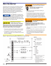
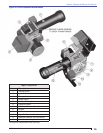
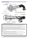
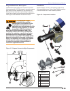
Refer to Figure 7 and Figure 10 for typical test
points and component locations.
y
y
y
y
y
Section: Start the Burner
Airfl ow proving switch – With the burner fi ring at
its lowest rate, loosen the tubing connection to the
airfl ow proving switch. A loss in air pressure at the
tubing should immediately cause the diaphragm
in the switch to open and recycle or lockout the
safeguard control.
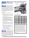
Low gas pressure switch – With the burner fi ring
and a manometer attached to a test port near
the low pressure switch, gradually close the main
leak test cock to shut off the gas supply. Note the
pressure at which the low gas pressure switch
opens and shuts the burner off. Manually reset the
switch. The low gas pressure switch should be set
at half of the normal supply pressure in the line.
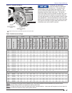
High gas pressure switch – With the burner fi ring
and a manometer attached to the test port nearest
the high pressure switch, gradually increase the
gas pressure until the high pressure switch opens
and shuts the burner off. Note the pressure and
manually reset the switch. The high gas pressure
switch should be set at one and one half times the
high fi re manifold pressure (see nameplate data in
Figure 1 or set switch as determined by testing).
Leak-test valve – With the burner fi ring and
manometer attached to the leak-test valve port, turn
the burner electrical switch off and observe that
the gas pressure does not increase after several
minutes. This proves total closure of the main gas
valve.
Flame safeguard safety lockout – Simulate a
fl ame failure by turning the main gas supply off. The
control should shut the burner off on safety within
the safety lockout time.
Flame sensor circuit (fl ame rod) – With the
burner power switch turned off, refer to the wiring
diagram supplied with the control and locate the
sensor connection terminals. Place DC voltmeter
probes in the fl ame amplifi er test jacks. With the
burner fi ring, the fl ame signal should be steady and
at least 1.25 VDC.
Flame sensor circuit (UV scanner) – With the
burner power switch turned off, refer to the wiring
diagram supplied with the control and locate the
sensor connection terminals. Place DC voltmeter
probes in the fl ame amplifi er test jacks. With the
burner fi ring, the fl ame signal should be steady and
at least 1.25 VDC.
4.
5.
6.
7.
8.
9.
10.
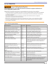
Check operation and safety controls