


30
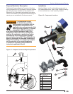
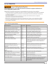
Section: Burner Confi gurations
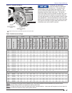
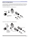
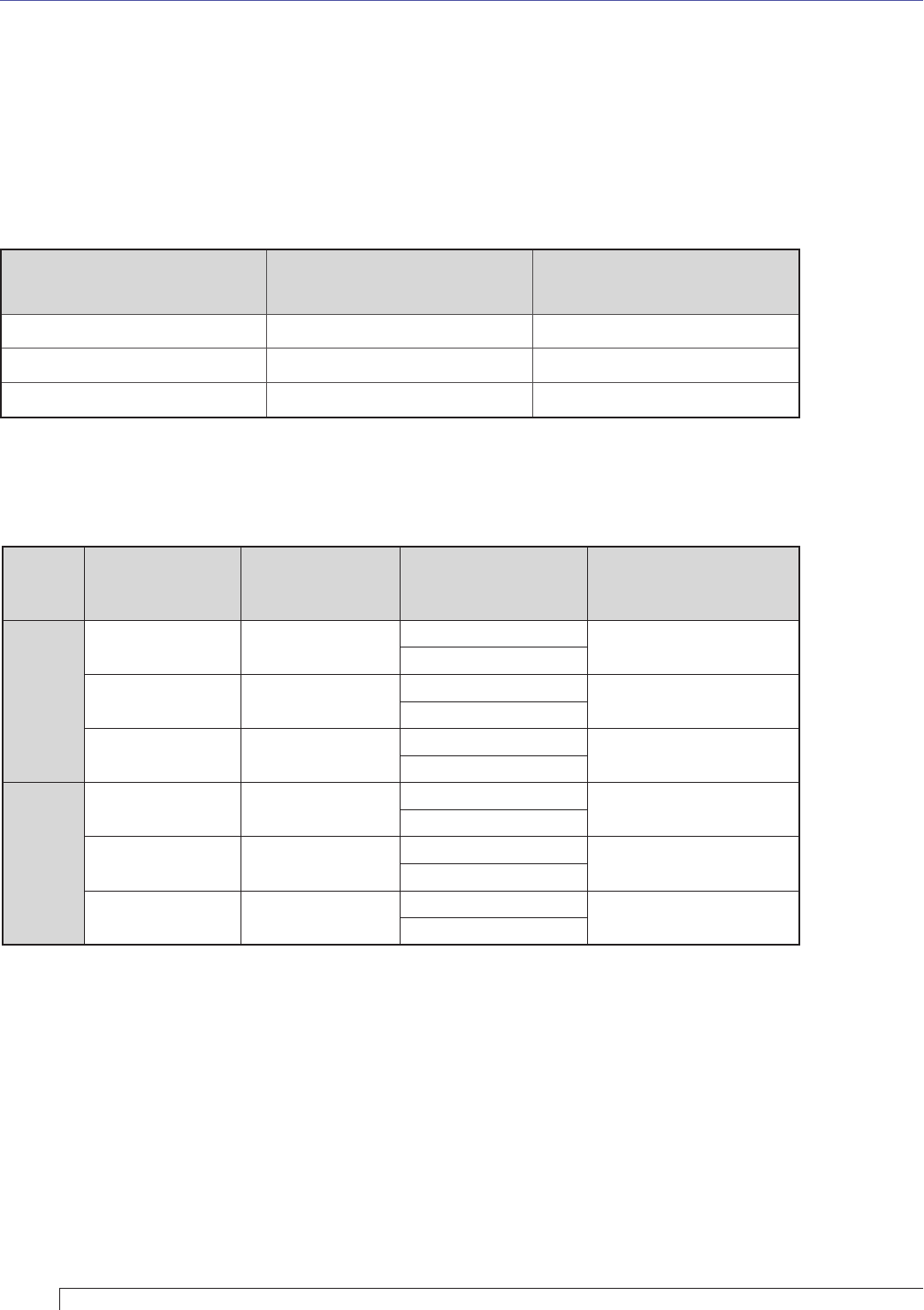
The table below shows proven combinations of the components and the nominal fi ring rate ranges they serve. These
combinations may vary and may be used outside of the nominal listed ranges based on results of specifi c applications
tests conducted for OEM appliance manufacturers.
Burner Model
Air Tube
Shroud
Gas Gun
Assembly
Nominal
Capacity, MBH
CG10
Chassis
CG10.1 31728
CG10.1S
300-378
CG10.1
CG10.2 31728
CG10.2S
379-476
CG10.2
CG10.3 31728
CG10.3S
477-600
CG10.3
CG10 A or B
Chassis
CG10.4 32297
CG10.4S
601-756
CG10.4
CG10.5 32297
CG10.5S
757-952
CG10.5
CG10.6 32297
CG10.6S
953-1200
CG10.6
Note: “s” suffi x refers to the Step Spud Design
Burner Confi gurations
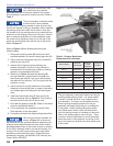
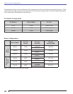
Air Platform Confi gurations
Air Platform Blower Wheel Air Inlet
CG10 21448 189 Air Guide
CG10A 21339 32336 Straight Inlet
CG10B 21339 178 Air Guide