


17
CG10 Burner Manual
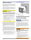
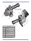
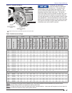
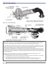
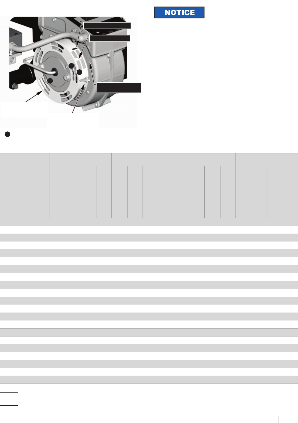
Figure 11. Shutter and Band
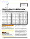
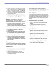
Table 2. Initial burner settings
Furnace Pressure 0” W.C. 0.25” W.C. 0.50” W.C. 1.00” W.C.
Firing Rate MBH
Burner Model
Running Manifold
Gas Press. in WC
Low Fire Start Gas
Press. in WC
Shutter Setting
Band Setting
Running Manifold
Gas Press. in WC
Low Fire Start Gas
Press. in WC
Shutter Setting
Band Setting
Running Manifold
Gas Press. in WC
Low Fire Start Gas
Press. in WC
Shutter Setting
Band Setting
Running Manifold
Gas Press. in WC
Low Fire Start Gas
Press. in WC
Shutter Setting
Band Setting
Stepped Spud Head Confi guration
300 CG10.1S 1.0 0.5 3 0 1.3 0.6 3 0 1.5 0.8 4 0 2.0 1.0 6 0
350 CG10.1S 1.4 0.7 4 0 1.6 0.8 4 0 1.9 0.9 5 0 2.4 1.2 7 0
400 CG10.2S 1.1 0.5 4 0 1.3 0.7 4 0 1.6 0.8 5 0 2.1 1.0 6 0
450 CG10.2S 1.4 0.7 5 0 1.7 0.8 6 0 1.9 1.0 7 0 2.4 1.2 9 0
500 CG10.3S 1.2 0.6 6 0 1.5 0.7 7 0 1.7 0.9 8 0 2.2 1.1 10 1
550 CG10.3S 1.3 0.7 8 0 1.6 0.8 9 0 1.8 0.9 10 0 - - - -
600 CG10.4S 2.5 1.3 5 0 2.8 1.4 6 0 3.0 1.5 7 0 3.5 1.8 9 0
700 CG10.4S 3.4 1.7 7 0 3.6 1.8 9 0 3.9 1.9 10 0 4.4 2.2 10 3
800 CG10.5S 3.1 1.6 8 0 3.4 1.7 9 0 3.6 1.8 10 1 4.1 2.1 10 3
900 CG10.5S 4.0 2.0 10 1 4.2 2.1 10 2 4.5 2.2 10 4 5.0 2.5 10 6
1000 CG10.6S 3.2 1.6 10 0 3.4 1.7 10 2 3.7 1.8 10 3 4.2 2.1 10 6
1100 CG10.6S 3.9 1.9 10 2 4.1 2.1 10 4 4.4 2.2 10 5 4.9 2.4 10 10
1200 CG10.6S 4.6 2.3 10 6 4.9 2.4 10 8 5.1 2.6 10 10 - - - -
Spinner Head Confi guration
300 CG10.1 1.5 0.8 3 0 1.8 0.9 3 0 2.0 1.0 4 0 2.5 1.3 5 0
350 CG10.1 2.0 1.0 5 0 2.3 1.1 6 0 2.5 1.3 8 0 3.0 1.5 10 1
400 CG10.2 1.6 0.8 4 0 1.8 0.9 4 0 2.1 1.0 5 0 2.6 1.3 6 0
450 CG10.2 2.0 1.0 4 0 2.2 1.1 4 0 2.5 1.2 5 0 3.0 1.5 8 0
500 CG10.3 1.5 0.8 5 0 1.8 0.9 5 0 2.0 1.0 6 0 2.5 1.3 8 0
550 CG10.3 1.9 0.9 7 0 2.1 1.1 8 0 2.4 1.2 9 0 2.9 1.4 10 1
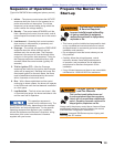
Notice: The settings in this chart are for reference only. The actual conditions at the installation may require further
adjustment by the fully qualifi ed and experienced start-up technician.
Notice: The light-off rate must not be set below the low fi re recommendation. Lower rates will lengthen the time it takes for
gas to get to the burner head and may cause ignition failures.
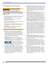
ADJUSTMENT SCALE
(FOR SHUTTER AND BAND)
BAND INDICATOR MARK
SHUTTER INDICATOR
SHUTTER
(for low rate adjustments)
adjust this with band fully
CLOSED
AIR BAND
(for high rate adjustments)
adjust this with shutter fully
OPEN
=
Tighten locking screws securely after adjustments have been made
◄
◄
◄
◄
The shutter and band both
control the amount of fl ow area
available for air inlet to the burner. The greater their
combined fl ow area, the higher the fi ring rate. The
primary differences between the two are their ease of
adjustment and their total airfl ow area. The shutter
turns more easily and has a smaller net fl ow area. As a
result we have found the shutter to be better suited for
low rate adjustments, and the band better suited for high
rate adjustments. We recommend that at low rates the
band be left completely closed until the shutter has been
fully opened, and that for higher rates the shutter is left
completely open as the band is opened.
Section: Start the Burner