


6104 BCF3 R02 Page 9
Install two high-quality shut-off valves in accessible
locations on the oil supply line. Locate one valve close
to the tank. Locate the other valve close to the burner,
upstream of the fuel fi lter.
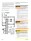
Burner fuel fl ow
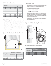
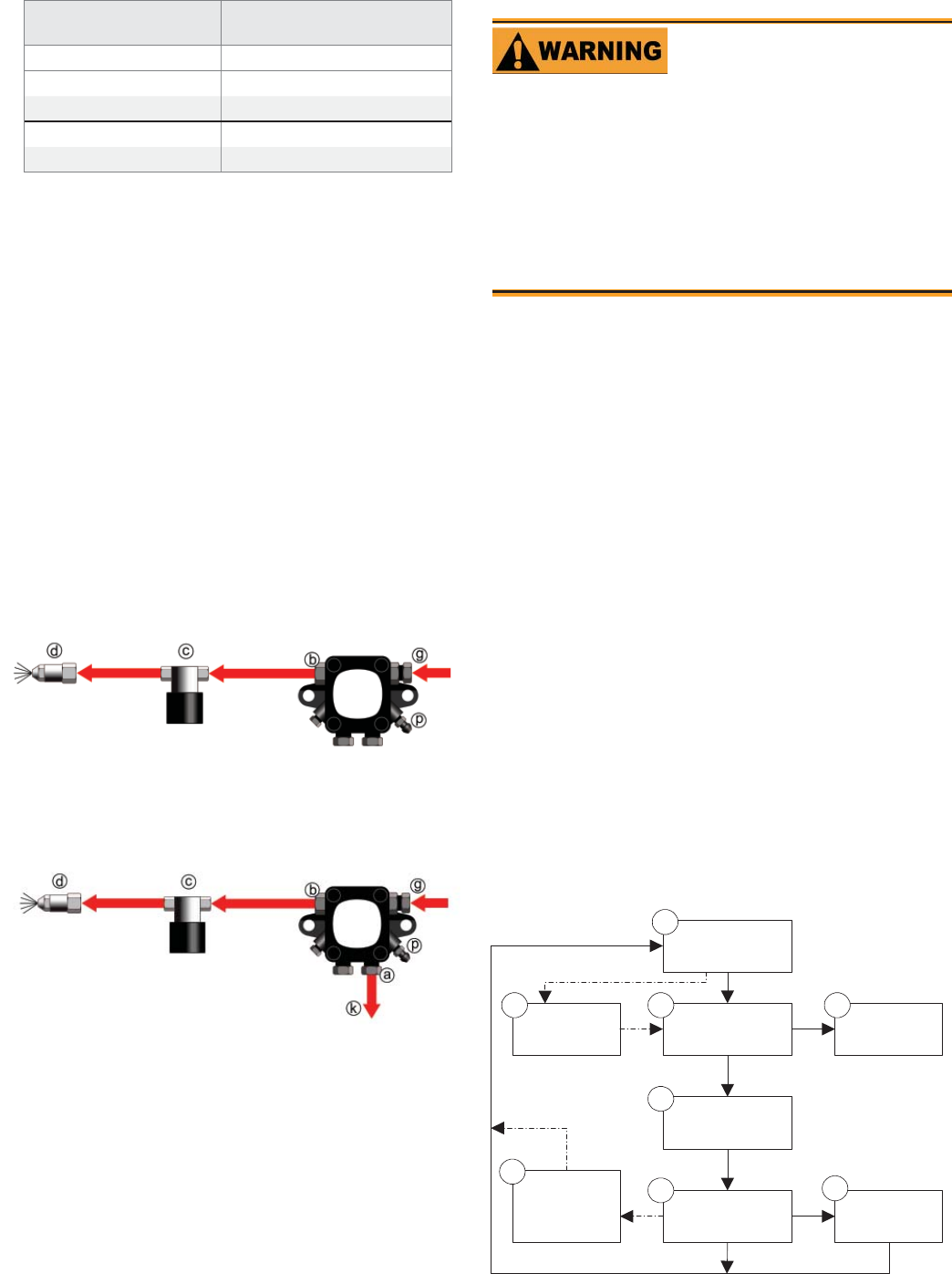
One-pipe systems – See Figure 7 for the fuel fl ow path.
Figure 7 is based on type B fuel unit.
Oil supply connects to one of the fuel unit inlet ports.
Two-pipe systems – See Figure 8 for the fuel fl ow paths
for two-pipe oil systems.
Figure 8 is based on type B fuel unit .
Oil supply connects to one of the fuel unit inlet ports.
Oil return connects to the fuel unit return port. (Install
the by-pass plug in the fuel unit for two-pipe sys-
tems.)
y
y
y
y
y
y
y
Figure 7 - One-pipe oil fl ow with “B” pump
Figure 8 - Two-pipe oil fl ow with “B” pump
Fuel unit
model number
Gearset capacity
(gallons per hour)
A2EA-6520 17
A2VA-7116 17
A2YA-7916 20
B2VA-8216 21
B2YA-8916 25
Table 2 - Fuel unit gearset capacities
125-200 psig
125-200 psig
3502
125-200 psig
125-200 psig
3503
Nozzle pressure – The fuel unit nozzle port pressure
is factory set at 140 psig. Some original equipment
manufacturer burner applications may call for a lower
pressure to obtain a required fi ring rate. Do not change
this pressure unless directed to do so by the appliance
manufacturer.
y
Legend
a Return port
b Nozzle port
c Oil valve
d Nozzle & adapter
g Inlet port
k Return line to oil tank
p Air bleed valve
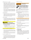
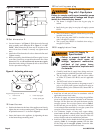
Wire the burner — R7184
Disconnect electrical power before installing or servic-
ing the burner.
Provide ground wiring to the burner, metal control en-
closures and accessories. (This may also be required to
aid proper control system operation)
Perform all wiring in compliance with the National
Electric Code ANSI/NFPA 70 (Canada CSA C22.1).
y
y
y
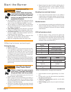
Electrical shock can cause severe personal in-
jury or death.
Electrical Shock Hazard
Install the burner and all wiring in accordance with the National
Electrical Code and all applicable local codes or requirements.
Wire the burner in compliance with all instructions provided by
the appliance manufacturer. Verify operation of all controls in
accordance with the appliance manufacturer’s guidelines.
S
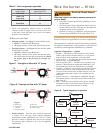
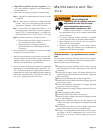
equence of operation — typical
1. Standby — The burner is idle, waiting for a call for heat.
When a call for heat is initiated, there is a 2- to 6-second
delay while the control performs a safe start check.
2. Valve-on delay — As applicable, the ignition and motor are
turned on for a 15-second prepurge.
3. Trial for ignition (TFI) — The fuel valve is opened, as ap-
plicable. A fl ame should be established within the 15-sec-
ond lockout time (30-second lockout time is available).
4. Lockout — If fl ame is not sensed by the end of the TFI, the
control shuts down on safety lockout and must be manu-
ally reset. If the control locks out three times in a row, the
control enters restricted lockout. Call a qualifi ed service
technician.
5. Ignition carryover — Once fl ame is established, the igni-
tion remains on for 10 seconds to ensure fl ame stability. It
then turns off.
6. Run — The burner runs until the call for heat is satisfi ed.
The burner is then sent to burner motor-off delay, as ap-
plicable, or it is shut down and sent to standby.
Standby
Trial for
ignition
Lockout
Recycle
Run
3
4
Ignition
carryover
Motor-off
delay
(postpurge)
8
6
7
5
Valve-on
delay
2
1
Figure 9. - Typical sequence of operation