


Page 12 6104 BCF3 R02
Start the Burner
Do not attempt to start the burner when excess oil has
accumulated in the appliance, the appliance is full of
vapor, or when the combustion chamber is very hot.
Do not attempt to re-establish fl ame with the burner
running if the fl ame becomes extinguished during start-
up, venting, or adjustment.
Vapor-Filled Appliance: Allow the unit to cool off and
all vapors to dissipate before attempting another start.
Oil-Flooded Appliance: Shut off the electrical power
and the oil supply to the burner and then clear all ac-
cumulated oil before continuing.
If the condition still appears unsafe, contact the Fire
Department. Carefully follow their directions.
Keep a fi re extinguisher nearby and ready for use.
y
y
y
y
y
y
Failure to follow these instructions
could lead to equipment malfunction
and result in heavy smoke emission,
soot-up, hot gas puff-back, fi re and
asphyxiation hazards.
Explosion and Fire
Hazard
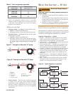
Starting the burner and venting air
Priming the pump
Initiate a call for heat
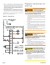
While the ignition is on, press and release the reset but-
ton on the R7184 control (hold 1/2 second or less). If
the control has not locked out since it’s most recent
complete heat cycle, the lockout time will be extended
to 4 minutes (45 seconds in earlier units), and the igni-
tion will remain on the entire heat cycle.
Bleed the pump until all froth and bubbles are purged.
If prime is not established within the extended lockout
time, the control will lock out. Press the reset button to
reset the control and return to the functions listed in the
previous step.
y
y
y
Do not allow oil to intermittently spray into a hot com-
bustion chamber while bleeding.
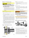
Install a gauge in the nozzle discharge port tubing or
fully open the pump bleed valve to prevent oil spray
from accumulating in the combustion chamber when
venting air from the fuel pump.
Ensure that all bubbles and froth are purged from the
oil supply system before tightening the pump air bleed
valve.
y
y
y
Failure to bleed the pump properly
could result in unstable combustion,
hot gas puff-back and heavy smoke.
Hot Gas Puff-back and
Heavy Smoke Hazard
Repeat the previous steps if needed, until the pump is
fully primed and the oil is free of bubbles. Then ter-
minate the call for heat, and the control will resume
normal operation.
Resetting from restricted lockout
If the control locks out three times in a row without a
complete heat cycle between attempts, the lockout be-
comes restricted. A qualifi ed service technician should
be called to inspect the burner.
Disable function
Any time the motor is running, press and hold the reset
button to disable the burner. The burner will remain off
as long as the button is held and will return to standby
when released
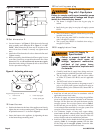
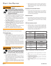
CAD cell resistance check
While the burner is fi ring, and after the ignition has
been turned off, press and release the reset button (hold
1/2 second or less) to check the cad cell resistance. The
LED will fl ash 1 to 4 times, depending on the cad cell
resistance (refer to the table below).
Number of LED
Flashes
Cad Cell Resistance (ohms)
1 Normal (0 to 400)
2 Normal (400 to 800)
3 Normal (800 to 1600)
4 Limited (1600-Lockout)*
* Lockout can occur above 4000 ohms.
LED Indicator Status
On Flame sensed
Off Flame not sensed
Flashing (1/2 sec off - 1/2
sec on)
Lockout/Restricted
Lockout
Flashing (2 sec off - 2 sec
on)
Recycle
Set combustion using instruments
Allow the burner to run for approximately 5 to 10 min-
utes.
Set the stack or over-fi re draft to the level specifi ed by
the appliance manufacturer.
Natural Draft Applications; typically over-fi re draft
is -0.01” or -0.02” w.c.
Direct Venting; typically may not require draft adjust-
ment.
y
y
y
y
1.
2.
y
y