


6104 BCF3 R02 Page 5
Combustion air supply
The burner requires combustion air and ventilation air for
reliable operation. Assure that the building and/or com-
bustion air openings comply with National Fire Protec-
tion Standard for Oil-Burning Equipment, NFPA 31. For
appliance/burner units in confi ned spaces, the room must
have an air opening near the top of the room plus one near
the fl oor, each with a free area at least one square inch
per 1,000 Btu/hr input of all fuel burning equipment in
the room. For other conditions, refer to NFPA 31 (CSA
B1139-M91 in Canada).
If there is a risk of the space being under negative pres-
sure or of exhaust fans or other devices depleting available
air for combustion and ventilation, the appliance/burner
should be installed in an isolated room provided with out-
side combustion air.
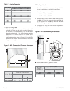
Clearances
With the burner installed in the appliance, there must be
adequate space in front of and on the sides of the burner
to allow access and operation. Verify that the clearance
dimensions comply with all local codes and with the ap-
pliance manufacturer’s recommendations.
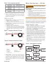
Fuel supply
The fuel supply piping and tank must provide #1 or #2 fuel
oil at pressure or vacuum conditions suitable for the fuel
unit (oil pump) on the burner. Refer to fuel unit literature
in the literature envelope in the burner carton to verify al-
lowable suction pressure.
y
y
y
y
If fuel supply is level with or higher than fuel unit —
When the fuel unit is not required to lift the oil, the instal-
lation is usually suitable for either a one-pipe or two-pipe
oil system. The oil pressure at the inlet of the fuel unit
must not exceed 3 psig.
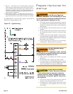
Refer to the Mount the Burner Section of this manual for
one-pipe or two-pipe fuel supply installation instructions.
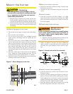
If fuel supply is below the fuel unit —
Use a two-pipe oil system when the fuel unit must lift the
oil more than 8 feet if burner is equipped with a B fuel
unit. The return line provided by the two-pipe system is
needed to purge the air from the fuel lines and minimize
the likelihood of air-related problems during operation.
y
y
y
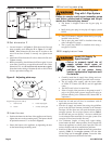
Oil Supply Pressure
Control Required
Damage to the pump, fi lter or other compo-
nent seals could cause possible oil leakage
and potential fi re hazard.
The oil supply inlet pressure to the fuel unit cannot
exceed 3 psig.
Ensure that a pressure-limiting device is installed in
accordance with the latest edition of the NFPA 31.
y
y
Nozzle pressure
The fuel unit nozzle port pressure is factory set at 140
psig. Some original equipment manufacturer burner appli-
cations may call for a lower pressure to obtain a required
fi ring rate. Do not change this pressure unless directed to
do so by the appliance manufacturer.
Vent system
The fl ue gas venting system must be in good condition and
must comply with all applicable codes.
Electrical supply
Verify that the power connections available are correct for
the burner. All power must be supplied through fused dis-
connect switches.
Verify burner components —
Burner, Model CF375
Air tube assembly
Mounting fl ange kit
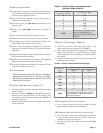
Oil nozzle, per Table 1 — Only 45° to 70° solid pattern
nozzles are recommended unless otherwise specifi ed by
appliance manufacturer. (See specifi c appliance recom-
mendation sheet or refer to OEM Spec Guide). Find the
required fi ring rate in the 150 psig column (factory-set fuel
unit pressure). Select the corresponding nozzle from col-
umn 1 (Rated gph @ 100 psig).
y
y
y
y
y
y
y
Use only nozzles having the brand, fl ow rate (gph), spray
angle and pattern specifi ed by the appliance manufac-
turer.
Follow the appliance manufacturer’s specifi cations for
the required pump outlet pressure for the nozzle, since
this affects the fl ow rate.
Nozzle manufacturers calibrate nozzle fl ow rates at
100 psig.
This burner utilizes pressures higher than 100 psig, so
the actual nozzle fl ow rate will be greater than the gph
stamped on the nozzle body. (Example: A 2.00 gph
nozzle at 150 psig = 2.45 gph.
For typical nozzle fl ow rates at various pressures
see accompanying chart.
y
y
y
Incorrect nozzles and fl ow rates
could result in impaired combustion,
under-fi ring, over-fi ring, sooting,
puff-back of hot gases, smoke and
potential fi re or asphyxiation haz-
ards.
Correct Nozzle and Flow
Rate Required