


6104 BCF3 R02 Page 11
Start-up checklist
Combustion air supply and venting have been inspected
and verifi ed to be free of obstructions and installed in ac-
cordance with all applicable codes.
Oil nozzle has been selected correctly and securely in-
stalled in the nozzle adapter.
Fuel unit by-pass plug has not been installed for one-
pipe oil system.
By-pass plug has been installed for two-pipe oil
system.
Fuel connection to nozzle line assembly is secure.
Dimension Z has been set per this instruction manual.
Fuel supply line is correctly installed, the oil tank is suf-
fi ciently fi lled, and shut-off valves are open.
Burner is securely mounted in appliance, with pressure
fi ring plate and gasket installed for pressurized chamber
application.
Appliance has been fi lled with water (boilers) and controls
have been operationally checked.
Burner has been installed in accordance with appliance
manufacturer’s instructions (when available).
Also refer to appliance manufacturer’s instructions (when
available) for start-up procedures.
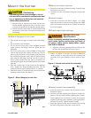
Z dimension
Should be set per the Set Z Dimension instructions
detailed earlier in this manual. The acorn nut (Fig-
ure 6, item c) should never be loosened once the Z
dimension is initially set.
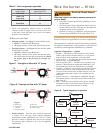
Initial head position (Figure 6)
The indicator plate assembly markings correspond to head
position settings.
Loosen the fastener (Figure 6, item d) and slide the
indicator plate until the number on the indicator plate
corresponds to the initial head setting listed in Table 3, for
the desired fi ring rate.
When the head position has been set, tighten the fastener
and the spline nut.
y
y
y
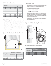
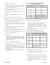
Table 3 - Initial indicator adjustment plate
settings (head position)
Approximate adjust-
ing plate setting
Firing rate, gph
0 1.65
1 1.75
3 2.00
4 2.50
5 3.00
6 3.50
NOTE
These settings are approximate,
and can vary depending on
actual job conditions and overfi re
pressure.
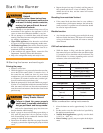
Firing rate,
gph
Approximate head settings
Shutter Band
1.65 5 0
1.75 10 2
2.00 10 4
2.50 10 5
3.00 10 6
3.50 10 8
NOTE
These settings are approximate, and can
vary depending on actual job conditions
and overfi re pressure.
Table 4 - Initial air shutter and band settings
Initial air settings (Table 4)
Loosen the air band and shutter, and adjust to the
approximate fi ring rate settings given in Table 4.
These initial settings should be adequate for starting the
burner. Once the burner is in operation, the air settings
will be adjusted for best performance as discussed later in
this manual.
Follow the procedures described later in this manual for
fi ne-tuning the air settings.
y
y
y
Set appliance limit controls
Set the appliance limit controls in accordance with the
appliance manufacturer’s recommendations.
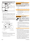
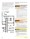
Prepare the fuel unit for air venting
To vent air from one-pipe oil systems, attach a clear hose
to the vent plug on the fuel unit. Provide a container to
catch the oil. Loosen the vent plug.
Vent the air as described in the next section under Start
the burner.
y
y
y