


6104 BCF3 R02 Page 13
High Effi ciency/Positive Pressure Appliances; also
vary from traditional appliances (see manufacturer’s
recommendations).
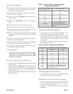
Follow these four steps to properly adjust the burner:
Step 1: Adjust the air shutter/band until a trace of smoke
is achieved.
Step 2: At the trace of smoke level, measure the CO
2
(or O
2
) . This is the vital reference point for further
adjustments. Example: 13.5% CO
2
(2.6% O
2
)
Step 3: Increase the air to reduce the CO
2
by 1.5 to 2
percentage points. (O
2
will be increased by approxi-
mately 2.0 to 2.7 percentage points.) Example: Re-
duce CO
2
from 13.5% to 11.5% (2.6% to 5.3% O
2
).
Step 4: Recheck smoke level. It should be Zero.
This procedure provides a margin of reserve air
to accommodate variable conditions.
If the draft level has changed, recheck the
smoke and CO
2 levels and readjust the burner,
if necessary
Once combustion is set, tighten all fasteners on air band,
air shutter and escutcheon plate.
Start and stop the burner several times to ensure satis-
factory operation. Test the primary control and all other
appliance safety controls to verify that they function ac-
cording to the manufacturer’s specifi cations.
Check the breech draft pressure against the appliance
manufacturer’s recommended setting (typically + 0.1”
W.C.). If the breech pressure is higher or lower than rec-
ommended level, adjust the appliance breech damper to
achieve the specifi ed setting. Recheck the smoke and
CO
2
levels. Adjust burner air if necessary.
y
3.
y
y
4.
5.
6.
Maintenance and Ser-
vice
Do not tamper with the burner or controls or make
any adjustments unless you are a trained and qualifi ed
service technician.
To ensure continued reliable operation, a qualifi ed
service technician must service this burner annually.
More frequent service intervals may be required in
dusty or adverse environments.
Operation and adjustment of the burner requires
technical training and skillful use of combustion test
instruments and other test equipment.
y
y
y
y
Tampering with or making incorrect
adjustments could lead to equip-
ment malfunction and result in
asphyxiation, explosion or fi re.
Annual Professional
Service Required
Annual service — by qualifi ed service techni-
cian
Have the burner inspected, tested and started at least annually
by a qualifi ed service technician. This annual test/inspection
should include at least the following:
Replace the oil supply line fi lter. The line fi lter cartridge
must be replaced to avoid contamination of the fuel unit
and nozzle.
Inspect the oil supply system. All fi ttings should be leak-
tight. The supply lines should be free of water, sludge and
other restrictions.
Remove and clean the pump strainer if applicable.
Replace the nozzle with the exact brand, pattern, gph, fl ow
rate and spray angle.
Clean and inspect the electrodes for damage, replacing
any that are cracked or chipped.
Check electrode tip settings. Replace electrodes if tips are
rounded.
Inspect the igniter spring contacts.
Clean the cad cell len’s surface, if necessary.
Inspect all gaskets. Replace any that are damaged or would
fail to seal adequately.
Inspect the combustion head and air tube. Remove any
carbon or foreign matter. Replace all damaged units with
exact parts.
Clean the blower wheel, air inlet, air guide, burner hous-
ing and static plate of any lint or foreign material.
If motor is not permanently lubricated, oil motor with a
few drops of SAE 20 nondetergent oil at each oil hole.
DO NOT over oil motor. Excessive oiling can cause mo-
tor failure.