


Page 6 6104 BCF3 R02
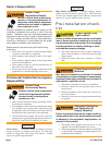
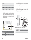
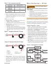
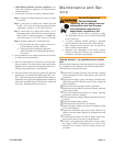
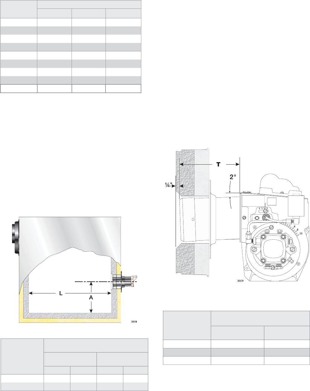
Figure 1. Min. Combustion Chamber Dimensions
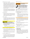
Verify fi ring rate
Refer to appliance manufacturer’s instructions (if
available) for fi ring rate and nozzle selection. Otherwise,
the maximum recommended fi ring rate for the burner
depends on the length of the fi ring chamber and the
distance from the burner center to the chamber fl oor.
Verify that the chamber dimensions are at least as large
as the minimum values given in Figure 1. If the appliance
dimensions are smaller than recommended, reduce the
fi ring rate accordingly.
y
Table 1 - Nozzle Capacities
Rated gph @
100 psig
Pressure - pounds per square inch
125 140 150
1.35 1.51 1.60 1.65
1.50 1.68 1.77 1.84
1.65 1.84 1.95 2.02
1.75 1.96 2.07 2.14
2.00 2.24 2.37 2.45
2.25 2.52 2.66 2.76
2.50 2.80 2.96 3.06
2.75 3.07 3.25 3.37
3.00 3.35 3.55 3.67
Firing Rate
Minimum Dimensions
(refractory-lined) (wet-base boilers)
ALAL
1.65 to 2.00 gph
5.5” 12.0” 5.5” 12.0”
2.00 to 3.75 gph
6.0” 15.0” 6.0” 20.0”
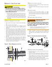
Air Tube
Length
(Dimension T)
A.T.C. Codes
(A.T.C. = Air Tube Combination)
Tube A Tube B
05.75” CF56KY CF56KZ
10.00” CF100KY CF100KZ
14.00” CF140KY CF140KZ
X Install burner with 2
o
pitch as shown.
X
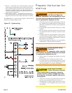
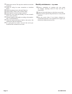
Figure 2 - Air Tube Mounting Dimensions
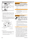
Verify air tube
The information in this section may be disregarded if the
air tube is supplied by the appliance manufacturer.
Two tube arrangements are available –
Tube A — 1.65 to 2.00 GPH
Tube B — 2.00 to 3.75 GPH
Maximum fi ring capacity depends on the fi rebox pressure.
Use Table 2 to verify the correct air tube type for the fi r-
ing rate required. Use Tube B only when Tube A cannot
provide the fi ring rate required.
See Figure 2 to verify the correct air tube length and air
tube combination code.
y
y
y
y