


7
CF1400/CF2300 Burner Manual
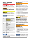
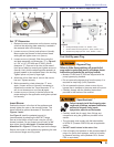
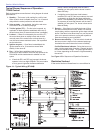
Stray Light
The control must detect a dark, no-fl ame condition
in order to start the burner or it will hold in the stray
light lockout mode.
Shield the burner view window from direct exposure
to intense light.
○
○
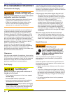
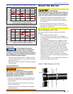
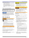
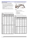
Mount the Burner
Mount Flange(s) on Air Tube
This section does not apply to burners with welded
fl anges.
Do not install air tube on burner.
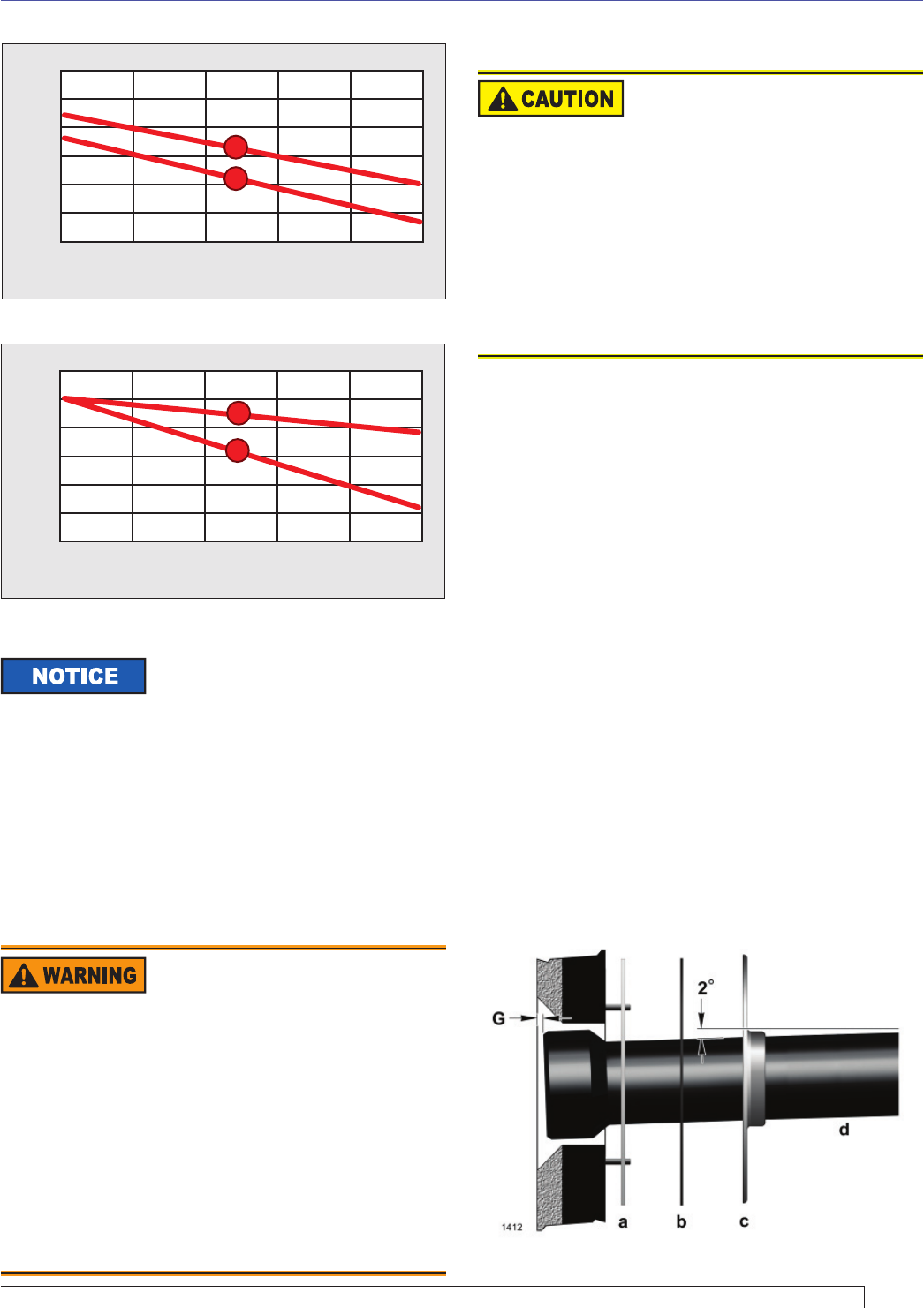
For non-pressure fi ring fl ange, refer to Figure 4:
Install gasket (item a) and fl ange (item c). Ignore the
next paragraph.
For pressure-fi ring fl ange, refer to Figure 4: Slide
gasket (item a) onto the air tube, making sure the
top of the air tube is up. Predrill holes in the pressure
fi ring plate (item b) to match the appliance studs.
Slide the pressure fi ring plate (item b) and fl ange
(item d) onto the air tube as shown. Wrap ceramic
fi ber rope (not shown) around the air tube and press
tightly into the inside diameter of the fl ange (item c).
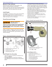
Slide the air tube (item d) into position in the
appliance front. Tighten the fl ange-mounting-stud
nuts. Set the insertion of the air tube so dimension G
is 1/4” nominal.
Pitch the air tube at 2° from horizontal as shown and
secure the fl ange to the air tube.
○
○
○
○
○
Dust and Moisture
Figure 4 – Mount fl ange(s) on air tube
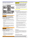
Protect Against Stray Light
Lockout Failure to follow these
instructions could cause loss of burner operation
resulting in no heat, an unplanned process interruption,
work stoppage and the potential for frozen plumbing or
other cold weather property damage.
Protect Against Dust and
Moisture
Wet, dusty environments could lead to blocked
air passages, corrosion damage to components,
impaired combustion performance and result in
asphyxiation, explosion or fi re.
This burner is designed for clean, dry installations.
Electrical controls are not protected against rain or
sprayed water.
Keep the installation clear of dust, dirt, corrosive
vapors, and moisture.
Protective covers and more frequent maintenance
may be required.
y
y
y
y
Protect the air tube from
overheating.
Overheating could cause damage to the air tube and
other combustion components leading to equipment
malfunction and impaired combustion performance.
The end of the air tube must not extend into the
combustion chamber unprotected unless it has
been factory-tested and specifi ed by the appliance
manufacturer.
Position the end of the air tube 1/4” back from
fl ush with the refractory inside entry wall to prevent
damage from overheating
y
y
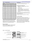
Section: Mount the Burner
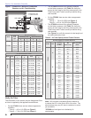
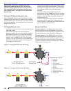
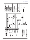
Figure 3b - Firebox Pressure: CF2300 with no Reserve Air
0.2 0.4 0.6 0.8
1.0
0.0
18
17
16
15
Firebox Pressure in Inches Water Column (W.C.)
Maximum Firing Rate U.S. GPH
KS
KG
19
20
21
Figure 3a - Firebox Pressure: CF1400 with no Reserve Air
0.2 0.4 0.6 0.8
1.0
0.0
12
11
10
9
Firebox Pressure in Inches Water Column (W.C.)
Maximum Firing Rate U.S. GPH
KE
KD
13
14
15