


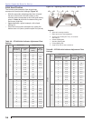
12
2
1
3
5
6
8
4
7
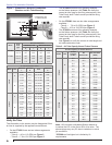
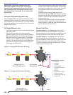
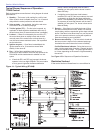
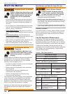
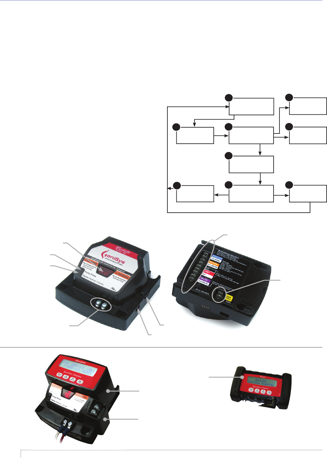
Standby
Motor-off delay
Valve-on delay
Trial for
ignition
Ignition carryover
Run
Lockout
Recycle
9
Pump
prime
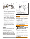
Run: With a fl ame established and the control
continuing to detect a fl ame, the burner will operate
in the RUN Mode until the load demand is satisfi ed
or a limit opens.
If terminals RC1 and RC2 are jumpered, the
burner operates in the Low-High-Off Mode.
The burner starts at Low, goes to High after the
fl ame stabilization period. Flame is extinguished
when the load is satisfi ed or a limit opens, and
the burner is sent to motor off delay.
If a high/low control has been wired between
terminals RC1 and RC2 the burner starts at
Low and is released to go High after the fl ame
stabilization period. It can repeatedly cycle
between low and high as necessary to meet
load demand until the load is satisfi ed or a limit
opens. The burner is then sent to Motor-off
Delay.
Recycle: If the fl ame is lost while the burner is
fi ring, the control shuts down the burner, enters a
60 second recycle delay, and repeats the ignition
sequence.
The control will continue to Recycle each
time the fl ame is lost, until it reaches a pre-set time
allotment. The control will then go into Hard Lockout
instead of recycle. This feature prevents excessive
accumulation of oil in the appliance fi ring chamber.
6.
a.
b.
7.
Motor-Off Delay: The oil solenoid valve is turned
off and the control delays turning the motor off
for the set motor-off delay time before the control
returns to standby.
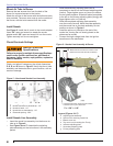
Pump Prime: The igniter and motor are on with the
oil solenoid valve energized for 4 minutes. During
Pump Prime mode, the cad cell is disregarded,
allowing the technician to prime the pump without
having to jumper the cad cell.
8.
9.
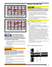
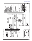
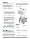
Section: Wire the Burner
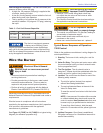
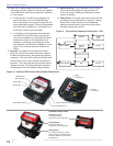
Display Module:
Permanent device for
programming and diagnostics
Alarm Module:
For adding isolated low voltage
alarm contacts to the base control.
See Alarm Module Instructions for
specifi cations.
Contractor’s Tool:
Hand-held device for
programming and diagnostics
Cad Cell
Connections
Wiring
Connections
Communication Port 2
Reset Button
with Red Light
Communication Port 1
Thermostat Terminals
Green Light
Yellow Light
Optional Components:
Figure 12 - GeniSys 7505 Control with Optional Components
Figure 11 - Typical Burner Sequence of Operation - 7505