


19
CF1400/CF2300 Burner Manual
Place the low-fi re hold switch in the high-fi re
position. The damper motor will begin to rotate
after four seconds.
Use combustion test instruments to adjust the
burner.
Adjust the air by moving the red cam to a lower
number until a trace of smoke is achieved with
CO
2
level as high as possible (lowest possible
O
2
).
Example: 13.5% CO
2
(2.5% O
2
) with a trace of
smoke.
Increase the air by increasing the red cam
number to reduce CO
2
by 2 percentage points
at a zero smoke level. (Increase O
2
by 3
percentage points at a zero smoke level.)
Example: Reduce CO
2
from 13.5% to 11.5%,
with zero smoke (or increase O
2
from 2.5% to
5.5%).
A margin of reserve air has been added to
accommodate variable conditions.
Check the breech draft pressure against the
appliance manufacturer’s recommended setting
(typically + 0.1” W.C.).
If the breech pressure is higher or lower than
recommended level, adjust the appliance breech
damper to achieve the specifi ed setting. Recheck
the smoke and CO
2
levels. Adjust burner air if
necessary.
Once all settings are complete and satisfactory,
proceed to ‘Set Low-fi re Air’.
Set Low-fi re Air
Move the low-fi re hold switch from the “High Fire
position” to the “Low Fire Hold” position.
The damper will return to the low-fi re air
setting.
Check the smoke and CO
2
(O
2
) levels.
Pull a smoke sample from the fl ue.
The sample should be clean (zero smoke level).
Check the CO
2
(O
2
) level:
CO
2
should be at 11 to 12% (O
2
at 5.9 to 4.5%).
If the CO
2
is less than 11% (O
2
more than 5.9%),
decrease the air and check the smoke level.
Operate the burner from low fi re to high fi re and
back to verify operation.
Turn the burner off. Wait one or two minutes (for
chamber to clear) and then turn on again to verify
starting characteristics.
Perform limit circuit performance test specifi ed
by appliance manufacturer to verify operation of
burner/appliance combination.
5.
6.
a.
b.
c.
7.
8.
9.
1.
a.
2.
a.
b.
c.
3.
4.
5.
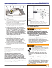
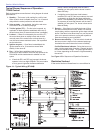
Operating the Burner
Move the low-fi re hold switch to the low fi re hold
position (to hold burner in low fi re when started).
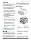
Verify that the air adjusting cam (Figure 17, item
d) has been set to the initial low-fi re air setting as
described under the ‘Initial Air Settings’ section.
Open the oil shutoff valves in the oil supply line to
the burner.
Set the thermostat (or operating control) to call for
heat.
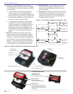
Close the line switch to the burner. The burner
motor should start immediately.
If the burner motor does not start, reset the motor
overload switch (if so equipped) and press the reset
switch of the burner primary control.
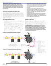
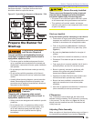
Vent the fuel unit as soon as the burner motor starts
rotating. (For GeniSys 7505 control refer to the
control manual for Priming the Pump procedure.)
To vent:
Attach a clear plastic tube to the air bleed valve
(Figure 9 or 10 as applies, item p).
Place the end of the tube in a container to catch
the oil. Then loosen the fuel unit air vent valve.
Tighten the air vent valve after all air has been
purged.
IF burner stops during venting —
The burner primary control will lockout if
fl ame is not established within its time limit.
This is typically 15 seconds for R7184B
primary controls, but may be less for other
fl ame supervisory controls.
The burner may lockout several times during
the period needed to purge all the air. To
extend air venting time, press the red reset
button for 1/2 second during the prepurge
cycle to continue purging.
IF burner stops after fl ame is established —
Additional venting is probably required.
Repeat the air venting procedure.
Once fl ame is steady, proceed to ‘Set High-fi re Air’.
Set High-fi re Air
Allow the burner to run at low fi re until the
appliance has warmed suffi ciently.
Visually check the fl ame. The fl ame should not be
dark orange or smoky. If the fl ame appears to be
smoking, increase the amount of air by readjusting
the damper indicator to a higher number.
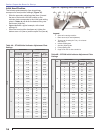
Once the appliance has warmed, the high-fi re
setting can be checked and adjusted.
Locate the approximate air adjusting plate setting
for high fi re in Table 4a or 4b.
1.
2.
3.
4.
5.
6.
7.
○
○
○
○
-
-
○
-
8.
1.
2.
3.
4.
Section: Start the Burner