


11
CF1400/CF2300 Burner Manual
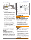
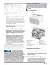
Low-fi re/high-fi re operation – The fuel unit nozzle port
pressure is factory set at 300 psig.
At high fi re, full pressure (300 psig) is applied at the
oil nozzle, causing full input.
At low fi re, the by-passing is done inside the fuel unit
when the by-pass valve operates.
This by-passing of oil reduces the oil pressure at the
nozzle (to between 125 psig and 175 psig), reducing
the input.
○
○
○
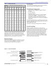
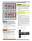
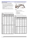
Model Fuel Unit Model Number Gearset Capacity (gph)
CF1400 B2TA-8245 23
CF2300 B2TA-8852 39
Table 3 – Fuel Unit Gearset Capacities
The fuel unit nozzle port pressure
is factory set at 300 psig. Some
original equipment manufacturer burner applications
may call for a lower pressure to obtain a required fi ring
rate. Do not change this pressure unless directed to do
so by the appliance manufacturer.
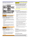
Install the burner and all wiring in accordance with the
National Electrical Code and all applicable local codes or
requirements.
Wire the burner in compliance with all instructions
provided by the appliance manufacturer. Verify operation
of all controls in accordance with the appliance
manufacturer’s guidelines.
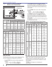
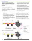
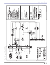
See Figure 13 (7505P) or 14 (7184B) for a typical wiring
diagram (for reference purposes only).
Wire the Burner
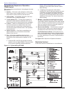
Typical Burner Sequence of Operation -
7505 Control
Refer to the appliance manufacturer’s wiring diagram for
actual specifi cations.
Standby: The burner is idle, waiting for a call for
heat.
Valve-On Delay: The igniter and motor are on while
the control delays turning on the oil solenoid valve
for the programmed time.
Trial For Ignition: The oil solenoid valve is
energized. A fl ame should be established within the
factory set trial for ignition time (lockout time).
Lockout: The control has shut down for one of the
following safety reasons:
The trial for ignition (lockout) time expired
without fl ame being established.
The cad cell detected fl ame at the end of the
Valve On Delay state.
To reset the control from lockout click the button
1-second.
NOTE: A recurrence of the above failure modes
or a failed welded relay check could cause the
control to enter a Hard Lockout state that must
be reset only by a qualifi ed service technician.
To reset from Hard Lockout, hold the reset
button for 15 seconds until the yellow light turns
on.
Ignition Carryover: Once fl ame is established,
the igniter remains on for 10 additional seconds to
ensure fl ame stability.
1.
2.
3.
4.
a.
b.
5.
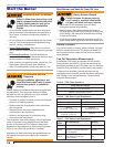
Fire or Explosion Hazard
Can cause severe injury, death, or property damage.
The control can malfunction if it gets wet, leading to
accumulation of explosive vapors.
Never install where water can fl ood, drip or
condense on the control.
Never use a control that has been wet - replace it.
y
y
y
Electrical Shock Hazard
Electrical shock can cause severe personal
injury or death.
Disconnect electrical power before installing or
servicing the burner.
Provide ground wiring to the burner, metal control
enclosures and accessories. (This may also be
required to aid proper control system operation)
Perform all wiring in compliance with the National
Electric Code ANSI/NFPA 70 (Canada CSA C22.1).
y
y
y
Incorrect Wiring Will Result in
Improper Control Operation
GeniSys 7505 Control wiring label colors may
not match the wire colors of the burner or other
manufacturers’ controls.
The GeniSys Control should be wired according to
the appliance manufacturer’s instructions.
y
y
Section: Wire the Burner