


22
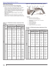
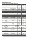
Item Part Name Description
CF1400
Part No.
CF2300
Part No.
1 Oil Valve Mounted on Junction Box 21789U 21789U
2 Knurled Nut All models 3666 3666
3 Adjusting plate assembly
w/ cast aluminum door
w/ stamped sheet-metal door
51213U
5201701U
51213U
5201701U
4 Fuel pump B2TA-8245 21313U 21313U
5 Damper motor 2-stage 750601U 750601U
6 Fuel lines Specify length – –
7 Air Proving Switch 2” W.C. 22181U 22181U
8 Timer Nozzle Valve Delay 21295U 21295U
9 Transformer 12,000 volt 51214 51214
10 Control Specify – –
11 Pedestal kit All models 51193 51193
12 Coupling hole plug use with threaded hole 32439U 32439U
13
Rear cover door as-
sembly
w/ cast aluminum door*
w/ stamped sheet-metal door*
5994U
5201301U
51204U
5201302U
14 Sight glass All models 31346 31346
15 Head assembly 5978 51203
16 Electrode assembly All models 51212 51212
17 Ignition leads
8-1/4” long
11-3/4” long
15-1/4” long
19-1/4” long
5990082
5990116
5990152
5990192
5990082
5990116
5990152
5990192
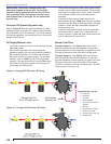
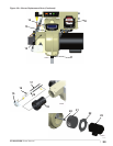
18 Air tube Refer to Figure 4
19 Nozzle line assembly Refer to Figure 5
20 Coupling B Pump 21290 21549
21 Blower wheel
CF1400 - 5.59” x 3.09”
CF2300 - 6.75” x 3.13”
21268U 21267U
22 Motor Mounting Flange N/A 31347U
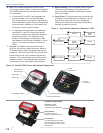
23 Motor
120/208-230 single phase
208-230/460 three phase
21401U
21638U
21402U
21499U
Motor relay (not shown)
120V single phase
208V single phase
Three phase
752804
7300
2194301
752804
7300
2194301
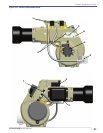
Adjustable fl ange See Figure 18 on previous page
* These doors are NOT interchangeable. Please specify when ordering.
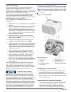
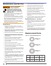
Replacement Parts
For best performance specify genuine Beckett replacement parts