


16
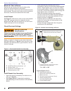
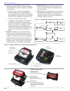
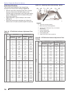
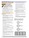
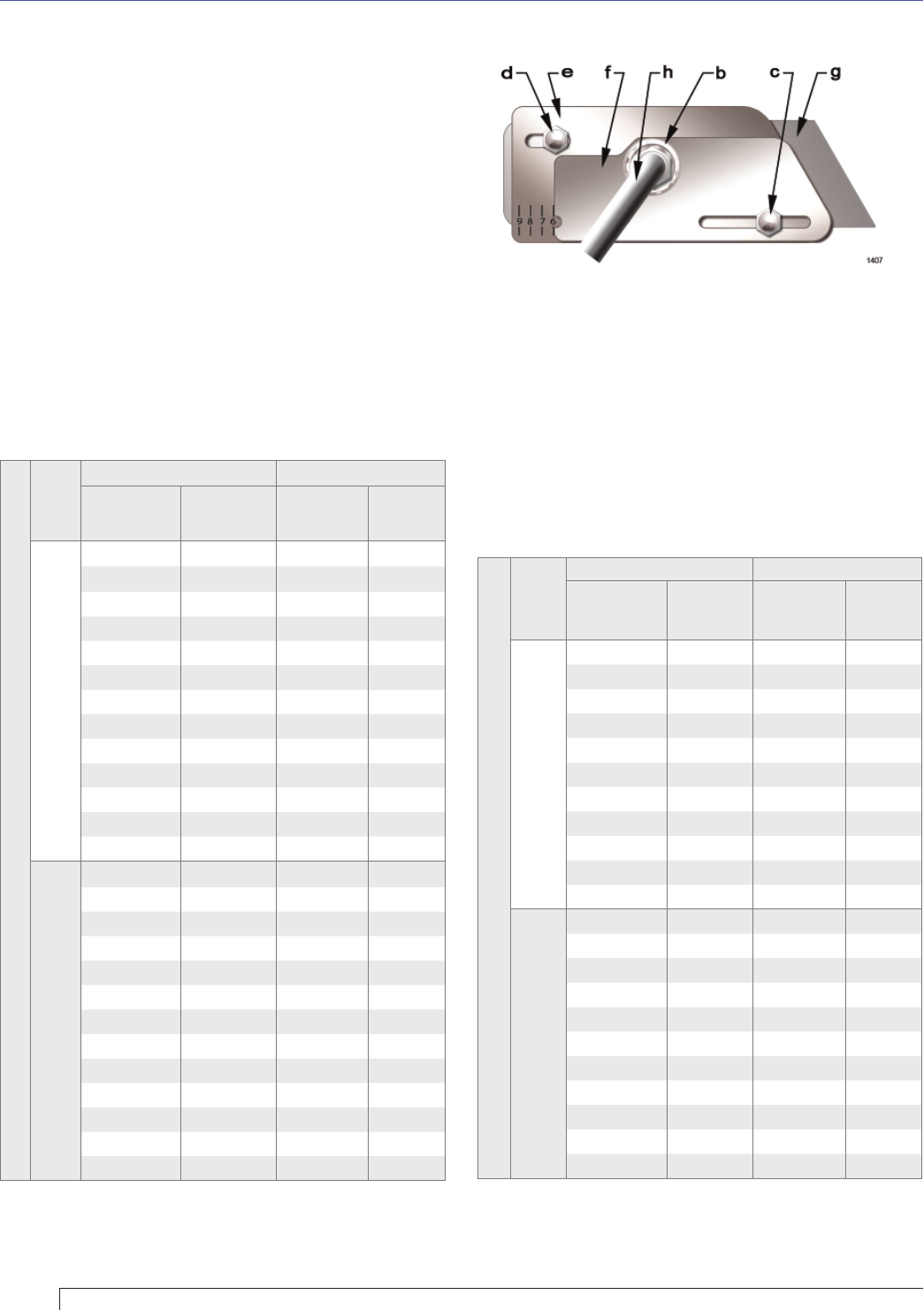
Figure 16 – Adjusting Plate Initial Setting, Typical
Table 4A – CF1400 Initial Indicator Adjustment Plate
Settings
CF1400
Tube
Head Position Damper Position
Approximate
Head Setting
Firing Rate
(gph)
Approximate
Air Damper
Setting
Firing
Rate (gph)
A
0 4.00 0 --
1 4.50 10 --
2 5.00 20 4.00
3 6.00 30 5.00
4 7.00 40 7.00
5 7.50 50 8.00
6 8.00 60 10.00
7 9.00 70 11.00
8 9.50 80 --
9 10.00 90 --
10 11.00 100 --
-- -- 110 --
-- -- 120 --
B
0 7.00 0 --
1 7.50 10 --
2 8.00 20 --
3 9.00 30 --
4 10.00 40 7.00
5 10.50 50 8.00
6 11.00 60 10.00
7 12.00 70 11.00
8 13.00 80 12.00
9 13.25 90 12.50
10 13.60 100 13.00
-- -- 110 13.25
-- -- 120 13.60
Table 4B – CF2300 Initial Indicator Adjustment Plate
Settings
CF2300
Tube
Head Position Damper Position
Approximate
Head Setting
Firing Rate
(gph)
Approximate
Air Damper
Setting
Firing
Rate (gph)
A
011.00--
1 12.0 10 7.0
2 13.0 20 10.0
3 14.0 30 13.0
4 15.0 40 14.0
5 16.0 50 15.0
6 17.0 60 16.0
7 18.0 70 17.0
8 19.0 80 18.0
9 20.0 90 19.0
-- -- 100 20.0
B
0 12.5 0 --
1 13.0 10 10.0
2 14.0 20 13.0
3 15.0 30 14.0
4 16.0 40 15.0
5 17.0 50 16.0
6 18.0 60 17.0
7 18.5 70 18.0
8 19.0 80 18.5
9 20.0 90 19.0
-- -- 100 20.0
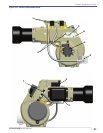
Legend
b Spline nut for securing nozzle line
c Bottom acorn nut (for head adjustments)
d Top acorn nut (for setting dim. Z only - do not loosen
after setting Z)
e Indicator adjusting plate
f Secondary adjusting plate
g Primary adjusting plate
h Copper oil line from oil valve to nozzle line
Initial Head Position
The indicator plate assembly (item e) markings
correspond to head position settings (Figure 16).
Slide the secondary adjusting plate (item f) toward
the rear of the burner until the number on the
indicator plate corresponds to the initial head setting
given in
Tables 4a and 4b for the desired fi ring rate
and burner (high-fi re).
Figure 16 shows a typical example, with a head
setting of 6.
When the head position has been set, tighten the
bottom acorn nut (item c) and the spline nut (item b).
○
○
○
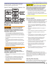
Section: Prepare the Burner for Start-up