


10
Special Note: The burner is shipped with a by-
pass plug installed in the fuel unit. For low/high
operation, the by-pass plug must be left in the fuel
unit, regardless of the fuel system used (one-pipe
with by-pass loop or two-pipe). Do not remove the
by-pass plug.
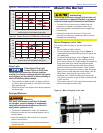
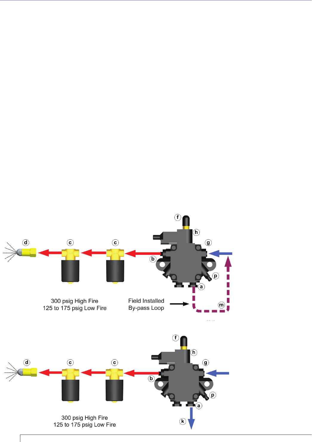
One-pipe Oil System By-pass Loop
Refer to Figure 9 (item m). Note the addition of a fi eld-
installed by-pass loop (use 3/8” copper tubing) from the
fuel unit Return port to the Inlet port. This line is required
for low/high operation. It simulates the fl ow of a two-pipe
system at the fuel unit.
Oil Supply/Return Lines
Install the oil tank and oil lines in accordance with all
applicable codes.
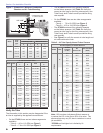
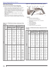
Size the oil supply and return lines using the
guidelines given in the fuel unit literature included in
the literature envelope. Oil line fl ow rate will equal
the burner rate for one-pipe systems. For two-pipe
systems, refer to Table 3 for the fuel unit gearset
capacity - the rate at which fuel is recirculated when
connected to a two-pipe system. Size two-pipe oil
lines based on this fl ow rate.
○
○
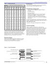
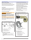
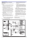
Legend (Figure 9 & 10)
a Return port
b Nozzle port
c Oil valves
d Nozzle & adapter
f
By-pass/Low fi re pressure
regulator
g Inlet port
h By-pass valve (“B” pump)
k Return line to oil tank
m One-pipe by-pass loop, 3/8”
p Air bleed valve
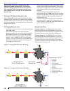
Figure 9 – One-pipe Oil Flow with “B” Pump
SK9940
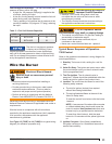
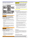
Figure 10 – Two-pipe Oil Flow with “B” Pump
SK9939
Use continuous lengths of heavy-wall copper tubing,
routed under the fl oor where possible. Do not attach
fuel lines to the appliance or to fl oor joists if possible.
This reduces vibration and noise transmission
problems.
Install an oil fi lter sized to handle the fuel unit
gearset fl ow capacity (Table 3) for two-pipe systems.
However, size the fi lter for the fi ring rate for one-pipe
systems. Locate the fi lter immediately adjacent to
the burner fuel unit.
Install two high-quality shutoff valves in accessible
locations on the oil supply line. Locate one valve
close to the tank. Locate the other valve close to the
burner, upstream of the fuel fi lter.
Burner Fuel Flow
One-pipe systems – See Figure 9 for the fuel fl ow
paths for high-fi re and low-fi re operation. The low-fi re
by-pass regulation is done internally for type B fuel units.
Oil supply connects to one of the fuel unit Inlet ports.
Two-pipe systems – See Figure 10 for the fuel fl ow
paths for high-fi re and low-fi re operation. The low-fi re
by-pass regulation is done internally for type B fuel units.
Oil supply connects to one of the fuel unit Inlet ports.
Oil return connects to the fuel unit Return port. Do NOT
install valves in the return line.
○
○
○
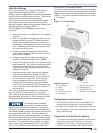
Section: Mount the Burner