


5
CF1400/CF2300 Burner Manual
The fuel unit nozzle port pressure is factory set at 300
psig. Some original equipment manufacturer burner
applications may call for a lower pressure to obtain a
required fi ring rate. Do not change this pressure unless
directed to do so by the appliance manufacturer.
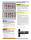
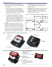
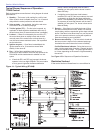
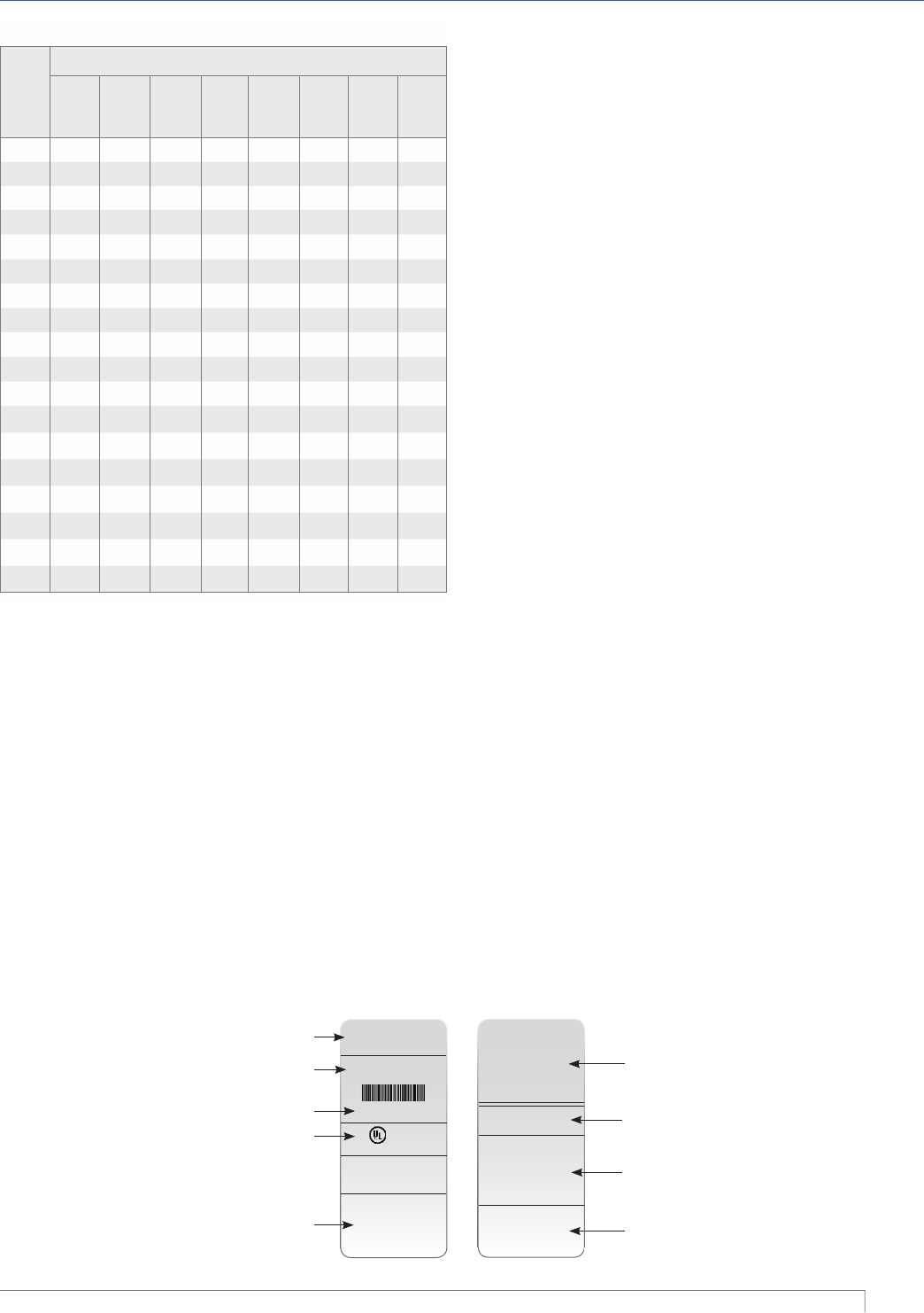
Electrical Supply
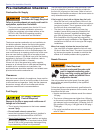
Verify that the power connections available are correct
for the burner. Refer to Figure 1. All power must be
supplied through fused disconnect switches.
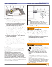
Figure 1 – Typical Nameplate
Vent System
The fl ue gas venting system must be in good condition
and must comply with all applicable codes.
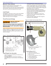
Verify Burner Components
Burner nameplate (Figure 1), Model CF1400 or
CF2300A
Air tube assembly
Mounting fl ange kit
Pedestal mounting assembly kit (recommended)
Oil nozzle, per Table 1 — Use only 45° to 70°
solid pattern nozzles unless otherwise shown by
appliance manufacturer or on the burner nameplate
rating label.
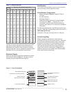
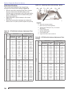
Find the required fi ring rate in the 300 psig column (high
fi re rate). Select the corresponding nozzle from column 1
(Rated gph @ 100 psig).
(Example: a 5.00 gph nozzle @ 300 psi = 8.66 gph)
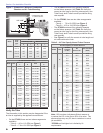
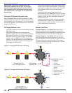
Verify Firing Rate
Refer to appliance manufacturer’s instructions (if
available) for fi ring rate and nozzle selection. Otherwise,
the maximum recommended fi ring rate for the burner
depends on the length of the fi ring chamber and the
distance from the burner center to the chamber fl oor.
Verify that the chamber dimensions are at least as
large as the minimum values given in Figure 2. If the
appliance dimensions are smaller than recommended,
reduce the fi ring rate accordingly.
○
○
○
○
○
Table 1 – Nozzle Capacities
Rated
gph
@100
psig
Pressure - Pounds per square inch
125 140 150 175 200 250 275 300
3.00 3.35 3.55 3.67 3.97 4.24 4.74 4.97 5.20
3.50 3.91 4.14 4.29 4.63 4.95 5.53 5.80 6.06
4.00 4.47 4.73 4.90 5.29 5.66 6.32 6.63 6.93
4.50 5.04 5.32 5.51 5.95 6.36 7.11 7.46 7.79
5.00 5.59 5.92 6.12 6.61 7.07 7.91 8.29 8.66
5.50 6.15 6.51 6.74 7.27 7.78 8.70 9.12 9.53
6.00 6.71 7.10 7.35 7.94 8.49 9.49 9.95 10.39
6.50 7.26 7.69 7.96 8.60 9.19 10.28 10.78 11.26
7.00 7.82 8.28 8.57 9.25 9.90 11.07 11.61 12.12
7.50 8.38 8.87 9.19 9.91 10.61 11.86 12.44 12.99
8.00 8.94 9.47 9.80 10.58 11.31 12.65 13.27 13.86
8.50 9.50 10.06 10.41 11.27 12.02 13.44 14.10 14.72
9.00 10.06 10.65 11.02 11.91 12.73 14.23 14.93 15.59
9.50 10.60 11.24 11.64 12.60 13.44 15.02 15.75 16.45
10.00 11.18 11.83 12.25 13.23 14.14 15.81 16.58 17.32
10.50 11.74 12.42 12.86 13.89 14.85 16.60 17.41 18.19
11.00 12.30 13.02 13.47 14.55 15.56 17.39 18.24 19.05
12.00 13.42 14.20 14.70 15.88 16.97 18.97 19.90 20.79
Section: Pre-Installation Checklist
LISTED
(FUEL) BURNER NO.P100000
SERIAL NUMBER
050214-00000
Control Circ: 120V/60Hz 4.5A
Motor Circ: 120V/60Hz 4.0A
Model “XX”
Series (Fuel) Burner
R.W. Beckett Corp.
Elyria, Ohio
Made in the U.S.A.
For use with Group 8 . . .
MP 1192 XX000 R00
X
X
X
X
X
X
XX000 R00
050214-00000
MFR’S SETTINGS
R.W. Beckett Construction &
Setting Data
R.W. Beckett Specifi cation
Number and Revision
Boiler Manufacturer and
Model, When Applicable
Additional Codes
General Model Information
Serial Number, Including Date Code
Rating Information
Approval Agency Symbols
Primary Group and Fuel