


15
CF1400/CF2300 Burner Manual
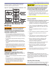
Prepare the Burner for
Start-up
Start-up checklist
Verify the following before attempting to start burner.
Combustion air supply and venting have been
inspected and verifi ed to be free of obstructions and
installed in accordance with all applicable codes.
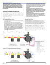
Fuel unit by-pass plug has not been installed for
one-pipe oil system, without a by-pass loop. (See
Figure 9.)
By-pass plug has been installed for two-pipe oil
system.
Fuel connection to nozzle line assembly is secure.
Dimension Z has been set per this instruction
manual.
Fuel supply line is correctly installed, the oil tank is
suffi ciently fi lled, and shut-off valves are open.
Burner is securely mounted in appliance, with
pressure fi ring plate and gasket installed for
pressurized chamber application.
Appliance has been fi lled with water (boilers) and
controls have been operationally checked.
Burner has been installed in accordance with
appliance manufacturer’s instructions (when
available).
Also refer to appliance manufacturer’s instructions
(when available) for start-up procedures.
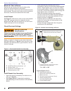
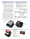
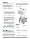
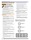
Z Dimension
The Z Dimension should be set per the instructions
detailed under the heading ‘Set Z Dimension’ previously
in this manual. The top acorn nut (Figure 16, item d)
should never be loosened once the Z dimension has
initially been set.
Adjusting Plate Assembly
Make sure spline nut (item b) and bottom acorn nut (item c)
are loose before proceeding to next section (Figure 16).
□
□
□
□
□
□
□
□
□
□
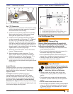
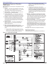
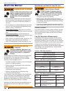
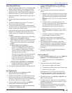
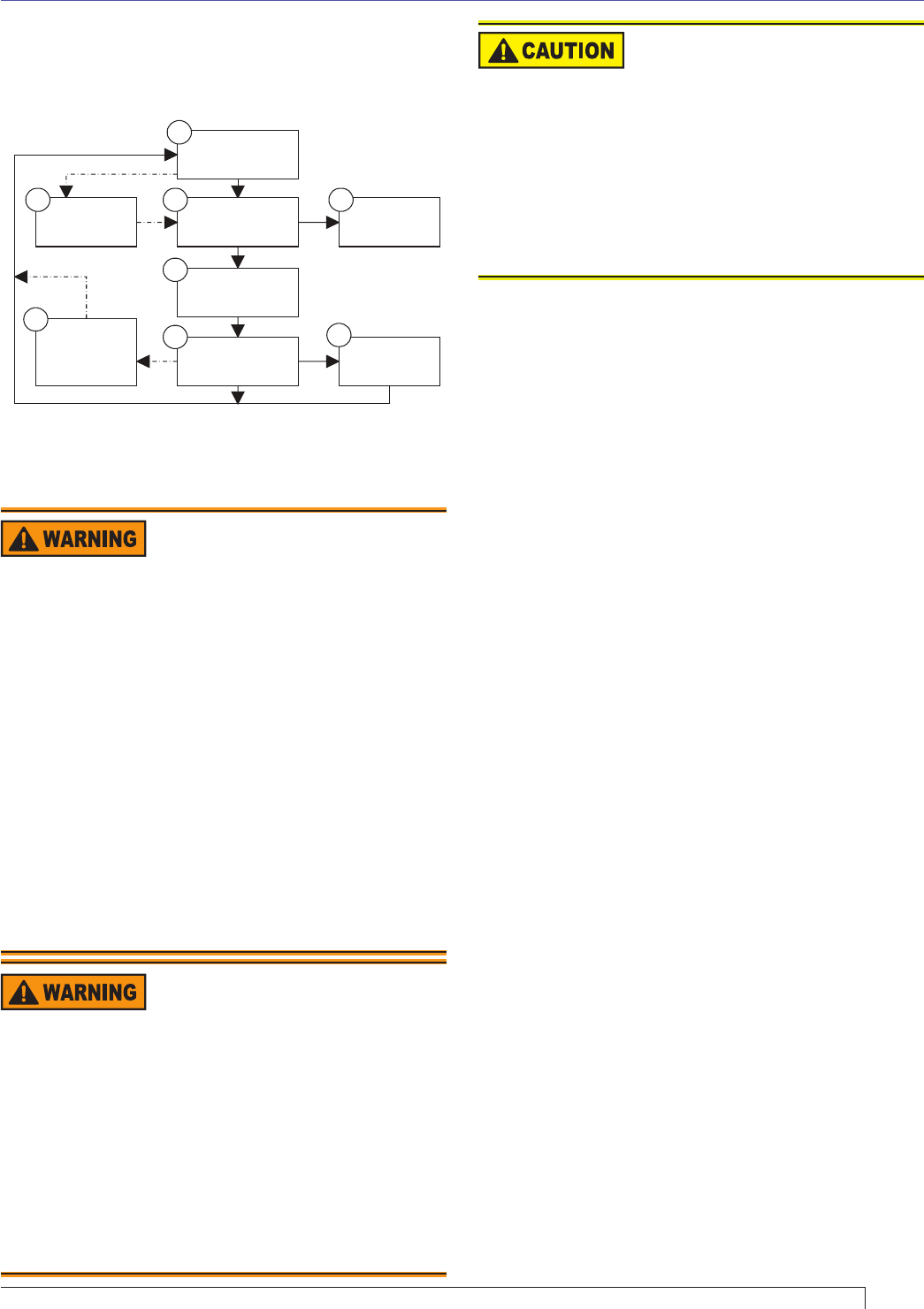
Standby
Trial for
Trial for
ignition
Lockout
RecycleRun
3 4
Ignition
carryover
Motor-off
delay
(postpurge)
8
6
7
5
Valve-on
delay
2
1
Section: Prepare the Burner for Start-up
Professional Installation
and Service Required
Incorrect installation and mishandling of start-up
could lead to equipment malfunction and result in
asphyxiation, explosion or fi re.
This burner must be installed and prepared for start-
up by a qualifi ed service technician who is trained and
experienced in commercial oil burner system installation
and operation.
Do not attempt to start the burner unless you are fully
qualifi ed.
Do not continue with this procedure until all items in
the “Prepare the burner for start-up” section have been
verifi ed.
Carefully follow the wiring diagrams, control instruction
sheets, fl ame safeguard sequence of operation, test
procedures and all appliance manufacturer’s directions
that pertain to this installation.
y
y
y
y
Do Not Bypass Safety
Controls
Tampering with, or bypassing safety controls
could lead to equipment malfunction and result in
asphyxiation, explosion or fi re.
Safety controls are designed and installed to provide
protection.
Do not tamper with, or bypass any safety control.
If a safety control is not functioning properly, shut
off all main electrical power and fuel supply to
the burner and call a qualifi ed service agency
immediately.
y
y
y
Keep Service Access
Covers Securely Installed
These covers must be securely in place to prevent
electrical shock, damage from external elements,
and protect against injury from moving parts.
All covers or service access plates must be in place
at all times except during maintenance and service.
This applies to all controls, panels, enclosures,
switches, and guards or any component with a cover
as part of its design.
y
y
Figure 15 - Typical Burner Sequence of Operation - 7184
complete heat cycle between attempts, the lockout
becomes restricted. A qualifi ed service technician
should be called to inspect the burner.