


9
AFII Burner Manual
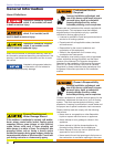
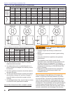
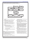
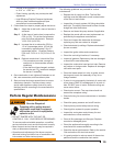
Figure 6. – Mounting Burner in Appliance
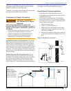
3 G
P
H
1
5
0
-
2
0
0
P
S
I3
4
5
0 R
P
M
4
G
P
H
GPH
1
0
0
-
1
5
0
10
0-15
0
P
S
I
PS
I
3
4
5
0
3450
R
P
M
R
P
M
B
Y
-
P
A
S
S
IN
L
E
T
A
2
E
A
-6
5
2
0
A2EA-6520
N
O.2
&
L
I
G
H
T
E
R
F
U
E
L
E
x
c
l
u
s
i
v
e
l
y
f
o
r
B
e
c
k
e
t
t
N
O.
2
F
U
E
L
Ma
d
e
b
y
S
u
n
te
c
Mad
eby
Sun
tec
I
N
L
E
T
Beck
ett
U
S
E
US
E
ON
L
Y
ONL
Y
W
IT
H
WI
TH
VA
L
V
E ON
D
E
L
AY
Section: Mount Burner on Appliance & Wire Burner
Mount Burner on Appliance
Verify that the air tube installed on the burner provides
the correct insertion depth. Refer to Figure 6.
Wire Burner
Burner packaged with appliance
Disconnect electrical power before installing or
servicing the burner.
Provide ground wiring to the burner, metal control
enclosures and accessories. (This may also be
required to aid proper control system operation.)
Perform all wiring in compliance with the National
Electrical Code ANSI/NFPA 70 (Canada CSA C22.1)
y
y
y
Electrical shock can cause severe
personal injury or death.
Electrical Shock Hazard
Refer to appliance manufacturer’s wiring diagram for
electrical connections.
Burner installed at jobsite
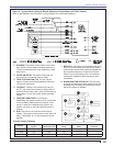
Refer to Figures 8a and 8b, for typical burner wiring,
showing cad cell primary controls. Burner wiring may
vary, depending on primary control actually used.
Refer to the appliance manufacturer’s wiring
diagram prior to connecting the burner wiring. All
wiring must be in accordance with the latest revision
of National Electric Code NFPA 70 and all local
codes and regulations. In Canada, all wiring is to be
in accordance with the Canadian Electrical Code,
Part 1.
The 7505 primary control with valve-on delay (pre-
time) and burner motor-off delay (post-time) requires
a constant 120 volts AC power source supplied to the
BLACK wire on the control. The RED wire goes to the
appliance limit circuit. Please note that other control
manufacturers may use different wire colors for power
and limit connections.
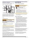
Special wiring required with covered burners
The mounting plate is not a conduit connection point.
Pass conduit and attached connector through the
opening in the mounting plate and attach it directly to the
burner-mounted 4x4 electrical box.
If attaching a burner cover to a previously installed
burner, attach the mounting plate and then slide the
conduit into the “J” shaped conduit slot.
○
○
○
The end of the air tube should normally be 1/4” back from
the inside wall of the combustion chamber. Never allow the
leading edge of the retention ring to extend into the chamber,
unless otherwise specifi ed by the appliance manufacturer.
Bolt the burner to the appliance using the factory-welded
fl ange.
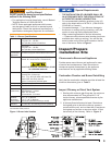
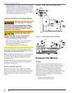
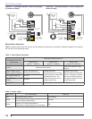
Connect Fuel Lines
The burner is shipped without the by-pass plug
installed.
Install the by-pass plug in two-pipe oil supply
systems ONLY.
y
y
Failure to comply could cause Immediate pump seal
failure, pressurized oil leakage and the potential for a
fi re and injury hazard.
Do Not Install By-pass Plug
with 1-Pipe System
The burner is supplied with either a one-stage pump
or a two-stage pump based on the oil supply system
requirements. Consult the instructions provided with the
pump for installation specifi cations.
When installing a one-pipe system, connect the inlet
line to the pump inlet. The fuel pump may be installed
with gravity feed or lift. The maximum allowable lift for a
single pipe installation is 8 ft.
When installing a two-pipe system, remove the 1/16”
pipe by-pass plug from plastic bag attached to fuel unit.
Remove 1/4” plug from return port. Insert and tighten
the by-pass plug. Attach return and inlet lines. The
return line should terminate approximately 3 to 4 inches
above supply line inlet. Failure to do this may introduce
air into the system and could result in loss of prime.