


16
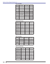
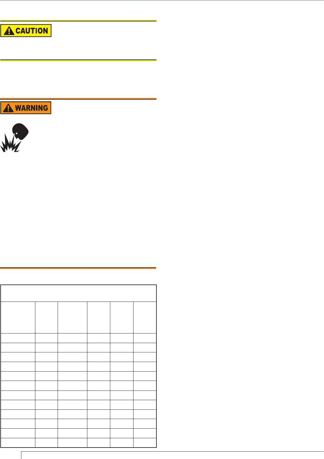
Table 4 - Nozzle Flow Rate by Size
Nozzle fl ow rate U. S. gallons per hour of No. 2 fuel oil
when pump pressure (psig) is:
Nozzle
size (rated
at 100
psig)
125
psi
140 psi
(factory
std.)
150
psi
175
psi
200
psi
0.40 0.45 0.47 0.49 0.53 0.56
0.50 0.56 0.59 0.61 0.66 0.71
0.60 0.67 0.71 0.74 0.79 0.85
0.65 0.73 0.77 0.80 0.86 0.92
0.75 0.84 0.89 0.92 0.99 1.06
0.85 0.95 1.01 1.04 1.13 1.20
0.90 1.01 1.07 1.10 1.19 1.27
1.00 1.12 1.18 1.23 1.32 1.41
1.10 1.23 1.30 1.35 1.46 1.56
1.20 1.34 1.42 1.47 1.59 1.70
1.25 1.39 1.48 1.53 - -
1.35 1.51 - - - -
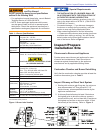
Shutting the Burner Off
Always keep the fuel oil
supply valve shut off if the
burner(s) is shut down for an extended
period of time.
Turn off all electric power to the burner. Note: There
could be more than one disconnect switch.
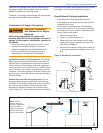
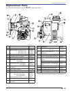
Removing Nozzle Line for Service
Correct Nozzle and Flow
Rate Required
Incorrect nozzles and fl ow rates could
result in impaired combustion, under-
fi ring, over-fi ring, sooting, puff-back of
hot gases, smoke and potential fi re or
asphyxiation hazards.
Use only nozzles having the brand, fl ow rate (gph), spray
angle and pattern specifi ed by the appliance manufacturer.
Follow the appliance manufacturer’s specifi cations for
the required pump outlet pressure for the nozzle, since
this affects the fl ow rate.
Nozzle manufacturers calibrate nozzle fl ow rates at
100 psig.
When pump pressures are higher than 100 psig, the
actual nozzle fl ow rate will be greater than the gph
stamped on the nozzle body. (Example: A 1.00 gph
nozzle at 140 psig = 1.18 gph)
Securely tighten the nozzle (90 torque inch pounds). For
typical nozzle fl ow rates at various pressures refer to Table 5.
y
y
Turn off power to burner before proceeding.
Disconnect copper oil connector tube from nozzle
line.
Loosen the screw that fastens the rear access door.
Remove splined nut.
Remove the nozzle line assembly from the burner,
being careful not to damage the electrodes or
insulators while handling. Stop halfway to remove
igniter/transformer wires.
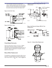
To replace the nozzle assembly, reverse the
above steps. “HLX” head air tubes – Be sure stop
screw is fastened securely. Seat stop screw on
back of choke ring to set the position of the head.
“FBX” head air tubes – Use T gauge to set the “Z”
dimension to 1-
1/8” +/- 1/32”
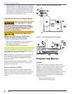
Nozzle Installation
Perform the following steps when replacing a nozzle.
Remove the nozzle line assembly to gain access to
the nozzle.
Use a 3/4” open-end wrench to hold the nozzle
adapter. DO NOT attempt to remove or replace
the nozzle without securing the adapter, as nozzle
alignment could be seriously affected.
Do not squeeze the electrodes when handling the
nozzle line assembly. Excessive force could change
the electrode tip settings or damage the ceramic
electrode insulators.
Use a 5/8” open-end wrench to carefully remove the
existing nozzle.
Inspect the nozzle adapter before installing the
new nozzle. If it is grooved or scratched on the
sealing surface, replace the nozzle line assembly.
If the surface is damaged, oil could leak at the
nozzle to adapter joint, causing serious combustion
problems.
Protect the nozzle orifi ce and strainer when
installing. If the orifi ce gets dirt in it or is scratched,
the nozzle will not function properly.
To install a new nozzle, place a 3/4” open-end
wrench on the nozzle adapter. Insert the nozzle
into the adapter and secure fi nger tight. Finish
tightening with a 3/8” open-end wrench. Use care
to avoid bending the burner head support legs or
electrodes.
Do not over-torque the nozzle when installing. This
will cause deep grooves in the nozzle adapter,
preventing a seal when a new nozzle is installed.
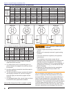
Carefully check and realign the electrode tips after
replacing a nozzle, ensuring the electrode settings
comply with Figure 11a or 11b.
1.
2.
3.
4.
5.
6.
1.
2.
3.
4.
5.
6.
7.
8.
9.
Section: Perform Regular Maintenance