


10
Burner Controls
GeniSys Model 7505 Control
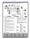
Wiring
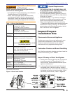
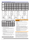
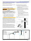
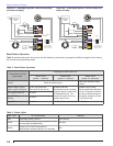
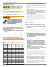
Figure 7 - 7505 Control
Features
Thermostat / Operating and Limit Control
Compatible
Welded Relay Protection
Limited Recycle
Limited Reset
3 Status Lights
Valve-On Delay / Motor-Off Delay (Field
programmable with 52067 GeniSys Display)
15 Second Lockout Time
Interrupted or Intermittent Duty Ignition
Technician Pump Priming Mode
Disable Function
Communication Ports
○
○
○
○
○
○
○
○
○
○
○
Section: Burner Controls
The control can malfunction if it gets wet, leading to
accumulation of oil or explosive oil vapors.
Never install where water can fl ood, drip or
condense on the control.
Never use a control that has been wet - replace it.
y
y
y
Can cause severe injury, death, or property
damage.
Fire or Explosion Hazard
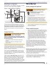
Follow the appliance manufacturer’s wiring diagrams
and note all required safety controls.
Typical safety controls include high temperature or
pressure limits, low water cutoffs, pressure relief
valves and blocked fl ue sensing switches.
Verify all limit and safety controls are installed
and functioning correctly, as specifi ed by the
manufacturer, applicable safety standards, codes
and all authorities having jurisdiction.
Ensure that the appliance is free of oil and oil vapor
before starting or resetting the burner.
y
y
y
y
All heating appliances must have HIGH
LIMIT protection to interrupt electrical
power and shutdown the burner if operating
or safety controls fail and cause a runaway
condition.
Explosion, Fire, Scald, and
Burn Hazard
Incorrect Wiring Will
Result in Improper Control
Operation
GeniSys wiring label colors may not match the wire
colors of the burner or other manufacturers’ controls.
The GeniSys Control should be wired according to
the appliance manufacturer’s instructions.
y
y
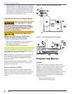
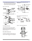
Display Module:
Permanent device for programming
and diagnostics
Alarm Module:
For adding isolated low voltage alarm
contacts to the base control. See Alarm
Module Instructions for specifi cations.
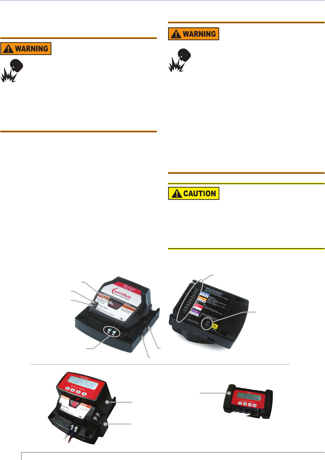
Contractor’s Tool:
Hand-held device for
programming and diagnostics
Cad Cell
Connections
Wiring
Connections
Communication Port 2
Reset Button with Red Light
Communication Port 1
Thermostat Terminals
Green Light
Yellow Light
Optional Components: