


15
AFII Burner Manual
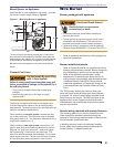
Perform Regular Maintenenance
The following guidelines are provided for routine
maintenance.
Replace the oil supply line fi lter. The line fi lter
cartridge must be replaced to avoid contamination
of the fuel unit and nozzle.
Inspect the oil supply system. All fi ttings should be
leak-tight. The supply lines should be free of water,
sludge and other restrictions.
Remove and clean the pump strainer if applicable.
Replace the nozzle with an exact replacement as
specifi ed by the appliance manufacturer.
Clean and inspect the electrodes for damage,
replacing any that are cracked or chipped.
Check electrode tip settings. Replace electrodes if
tips are rounded.
Inspect the igniter cables and connections.
Clean the cad cell grid surface, if necessary.
Inspect all gaskets. Replace any that are damaged
or would fail to seal adequately.
Inspect the combustion head and air tube. Remove
any carbon or foreign matter. Replace all damaged
units with exact parts.
Clean the blower wheel, air inlet, air guide, burner
housing and nozzle line assembly of any lint or
foreign material.
If motor is not permanently lubricated, oil motor with
a few drops of SAE 20 nondetergent oil at each oil
hole. DO NOT over oil motor. Excessive oiling can
cause motor failure.
Check motor current. The amp draw should not
exceed the nameplate rating.
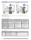
Check all wiring for secure connections or insulation
breaks.
Check the pump pressure and cutoff function.
Check primary control safety lockout timing.
Check ignition system for proper operation.
Inspect the vent system and chimney for soot
accumulation or other restriction.
Clean all fl ue passages and fl ue pipe. Replace
corroded or damaged pipes.
Clean the appliance thoroughly according to the
manufacturer’s recommendations.
Check the burner performance. Refer to the section
“Set combustion with test instruments”.
It is good practice to make a record of the service
performed and the combustion test results.
□
□
□
□
□
□
□
□
□
□
□
□
□
□
□
□
□
□
□
□
□
□
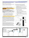
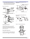
Natural Draft Applications; typically over-fi re draft
is -0.01” or -0.02” w.c.
Direct Venting; typically may not require draft
adjustment.
High Effi ciency/Positive Pressure Appliances;
also vary from traditional appliances (see
manufacturer’s recommendations).
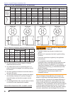
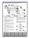
Follow these four steps to properly adjust the burner:
Step 1: Adjust the air dial until a trace of smoke is
achieved.
Step 2: At the trace of smoke level, measure the
CO
2
(or O
2
) . This is the vital reference
point for further adjustments. Example:
13.5% CO
2
(2.6% O
2
)
Step 3: Increase the air to reduce the CO
2
by
1.5 to 2 percentage points. (O
2
will be
increased by approximately 2.0 to 2.7
percentage points.) Example: Reduce
CO
2
from 13.5% to 11.5% (2.6% to 5.3%
O
2
).
Step 4: Recheck smoke level. It should be Zero.
This procedure provides a margin of
reserve air to accommodate variable
conditions.
If the draft level has changed, recheck
the smoke and CO
2
levels and readjust
the burner if necessary
Once combustion is set, tighten all fasteners on air
dial, rear access door, and escutcheon plate.
Start and stop the burner several times to ensure
satisfactory operation. Test the primary control
and all other appliance safety controls to verify
that they function according to the manufacturer’s
specifi cations.
○
○
○
3.
○
○
4.
5.
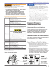
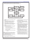
Annual Professional
Service Required
Tampering with or making incorrect
adjustments could lead to equipment
malfunction and result in asphyxiation,
explosion or fi re.
DO NOT TAMPER WITH THE UNIT OR
CONTROLS - CALL YOUR SERVICE PERSONNEL.
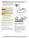
To ensure continued reliable operation, a qualifi ed
service technician must service this burner annually.
More frequent service intervals may be required in
dusty or adverse environments.
Operation and adjustment of the burner requires
technical training and skillful use of combustion test
instruments and other test equipment.
y
y
y
Section: Perform Regular Maintenance