


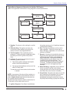
6
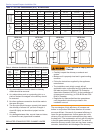
HB 6 slot
HC 9 slot
HD 6 slot
HE 9 slot
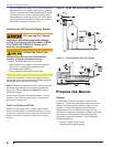
Any accumulation of soot or debris in chimney
offsets should be removed
Any obstructions such as a protruding joint or a
piece of broken tile wedged in the chimney should
be removed.
No other appliance connection should be made to
the same fl ue pipe.
The fl ue pipe should have an upward pitch toward
the chimney of at least 1/4” per foot of length. It
should fi t tightly and should not project into the
chimney.
Any leakage between tiles, around clean-out doors,
or around the vent pipe should be sealed.
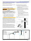
INSULATED STAINLESS STEEL CHIMNEY LINERS
3.
4.
5.
6.
7.
The new designs of high effi ciency oil furnaces and
boilers in conjunction with fl ame retention oil burners
are more effi cient. One result of increased effi ciency is
lower fl ue gas temperatures. As fl ue gases rise in the
chimney, they will cool and condense when they reach
the dew point. The condensation will mix with the sulphur
in the fl ue gases creating sulphuric acid. The acid will
attack the chimney mortar, brick and clay liners causing
corrosion, deterioration and blockage of the chimney.
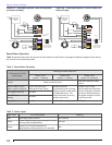
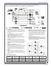
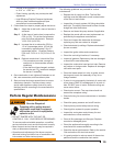
Table 2 – Air Tube Combinations (ATC) & Dimensions
ATC codes for usable air tube lengths dim. “A” (Figure 3) Firing rate range (gph)Min-Max
3” 5” 7” 9” ATC Code Head AFII 85 AFII 100 AFII 150
Adjustable
w/stop screw
Head Design
HLX30 HLX50 HLX70 HLX90 HB AF2-6 0.4-0.85 gph 0.65-1.00 gph 0.75-1.35 gph
HLX30 HLX50 HLX70 HLX90 HC AF2-9 N/A 0.65-1.00 gph 0.75-1.50 gph
HLX30 HLX50 HLX70 HLX90 HD AF2-6 0.40-0.85 gph 0.65-1.00 gph 0.75-1.10 gph
HLX30 HLX50 HLX70 HLX90 HE AF2-9 N/A 0.65-1.00 gph 0.75-1.35 gph
Head Design
- Fixed
FBX30 FBX50 FBX70 FBX90 HFXS FB0 0.40-0.65 gph 0.55-0.75 gph 0.75-1.00 gph
FBX30 FBX50 FBX70 FBX90 HGXS FB3 0.55-0.85 gph 0.55-1.10 gph 0.85-1.20 gph
FBX30 FBX50 FBX70 FBX90 HHXS FB4 N/A 0.75-1.10 gph 1.10-1.25 gph
FBX30 FBX50 FBX70 FBX90 HIXS FB6 N/A 0.85-1.15 gph 1.15-1.35 gph
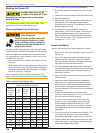
Table 3 – Minimum Combustion Chamber Dimensions (inches)
Firing
Rate
(gph)
Round
I.D.
Rectangular
Height
Floor to
nozzle
Width Length
0.50 8 7 8 12 5 to 6
0.75 9 8 9 12 5 to 6
1.00 10 9 10 12-1/2 5 to 6
1.25 11 10 11 12-1/2 5 to 6
1.50 12 11 12 13 6 to 7
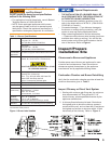
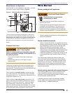
Section: Inspect/Prepare Installation Site
Carefully inspect the chimney or exhaust vent
system.
Make sure it is properly sized and in good working
condition.
Follow the instructions supplied by the appliance
manufacturer.
The installation must strictly comply with all
applicable codes, authorities having jurisdiction and
the latest revision of the National Fire Protection
Association Standard NFPA 31 for the installation of
chimneys and vent sizing, (or CSA-B139 and CSA-
B140 in Canada).
Regulation by these authorities take precedence
over the general instructions provided in this
installation manual.
y
y
y
y
y
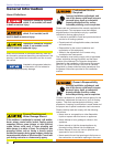
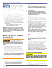
Fire, Smoke & Asphyxiation
Hazard