


17
AFII Burner Manual
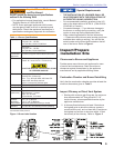
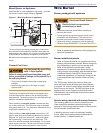
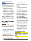
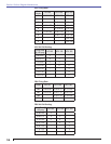
Figure 10a. HLX Air Tube
SK9639
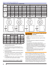
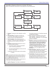
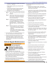
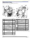
Figure 11a. Electrode Settings-HLX Air Tube
Combinations
1-1/2”
15/32”
3/32”
5/32”
1/4”
5/32”
Nozzle face to back of head
Stop
Screw
Do NOT overtighten
Clamp Screw
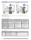
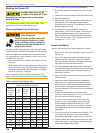
Figure 11b. Electrode Settings-FBX Air Tube
Combinations
SK9461
SK8263
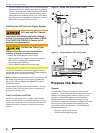
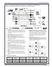
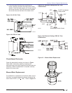
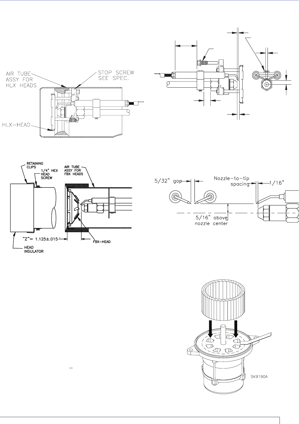
Figure 12. – Blower Wheel Replacement
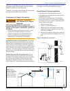
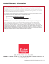
Figure 10b. FBX Air Tube
If the head was removed when replacing the
nozzle, carefully reconnect the head to the nozzle
adapter. Push the head support until it stops against
the nozzle shoulder. Verify the dimension between
the nozzle face and the back of the head is
5/32”.
10.
Check/Adjust Electrodes
Check the electrode tip settings, as shown in Figure
11a or 11b. If necessary, adjust by loosening the
electrode clamp screw and slide/rotate the electrodes as
necessary. When the adjustment is complete, securely
tighten the clamp screw.
Blower Wheel Replacement
For installation or replacement of a blower wheel, insure
that there is a space between the blower wheel and the
motor face of 0.062” (1/16” + 1/64”). Refer to Figure 12.
Section: Perform Regular Maintenance