


RWB 6104 BAFG R02 Page 9
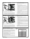
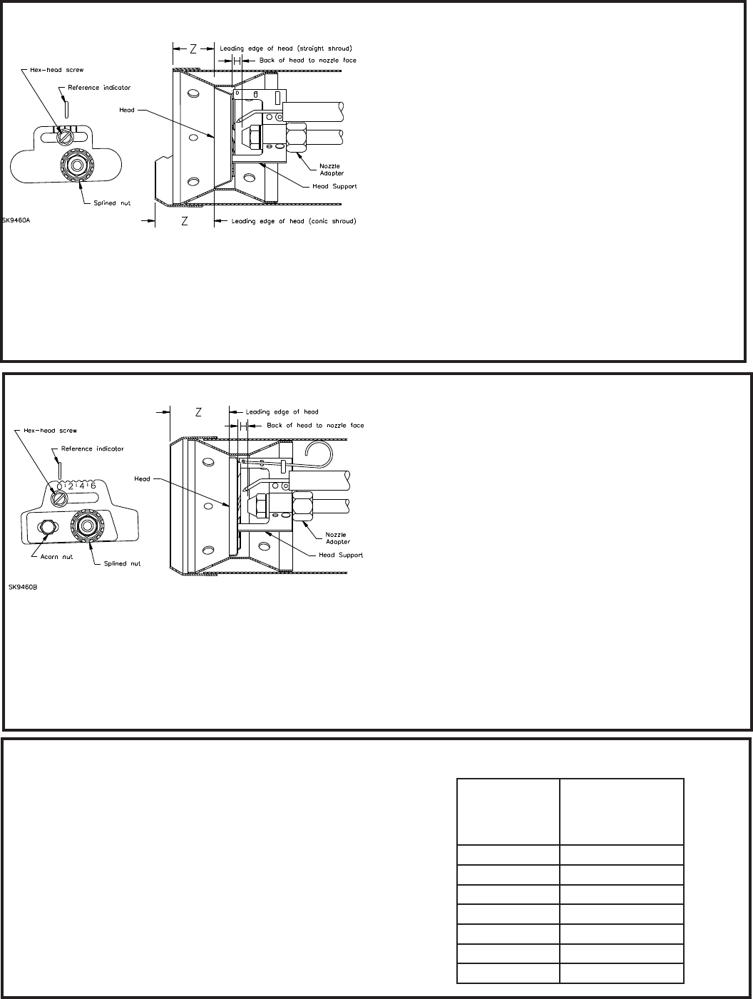
Check/Adjust ‘Z’ Dimension - L1 & L2
Heads
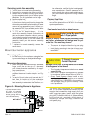
Check/Adjust ‘Z’ Dimension - V1 Heads
V1 Adjusting
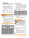
Plate Setting
AFG with V1
Head
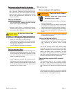
Burner Firing
Rates
0 0.75-1.00
1 1.00-1.50
2 1.50-1.75
3 1.75-2.00
4 2.00-2.25
5 2.25-2.50
6 2.50-2.75
Table for initial adjusting plate settings for V1
Head
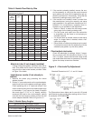
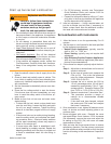
L1/L2 heads (see Table 7 and Figure 3 for dimensions)
1. See fi gure above. The important “Z” dimension is the distance from
the leading edge of the head to the end of the air tube. This distance
for L1 & L2 heads is 1-⅜” if the tube has a straight shroud or 1-¾” if
the air tube has a conic shroud. The “Z” dimension is factory set for
Set head position adjusting plate (V1 head only)
1. After setting “Z” dimension, loosen head adjusting plate hex head
screw and nozzle line splined nut. Move the nozzle line assembly until
the burner reference indicator lines up with the head adjusting plate
setting number given in Table shown below.
2. Tighten the hex head screw and splined nut. (DO NOT loosen the
acorn nut when setting head position.) Refer to the manufacturer’s in-
structions for OEM settings.
3. The position of the head affects air fl ow volume and pattern. For most
applications, the burner will perform satisfactorily with the air adjust-
ment plate setting of Table shown below.
4. If combustion results indicate the need for change, adjust the head po-
sition adjusting plate forward or back one position at a time to optimize
combustion.
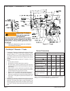
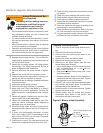
V1 heads (see Table below and Figure above for dimensions)
1. See fi gure above. The important “Z” dimension is the distance from
the leading edge of the head to the end of the air tube. This distance
for V1 heads is 1-¾”. The “Z” dimension is factory set for burners
shipped with the air tube installed. Even if factory set, verify that the
“Z” dimension has not been changed.
burners shipped with the air tube installed. Even if factory set, verify
that the “Z” dimension has not been changed.
2. Use the following procedure to adjust the “Z” dimension, if it is not
correct:
Turn off power to the burner.
Disconnect the oil connector tube from the nozzle line.
Refer to fi gure. Loosen the splined nut from the nozzle line.
Loosen the hex head screw securing the escutcheon plate to the
burner housing.
Place the end of a ruler at the leading edge of the head and, us-
ing a straight edge across the end of the air tube, measure the
distance to the end of the tube. A Beckett T501 gauge may also
be used.
Slide the nozzle line forward or back until this dimension is 1-⅜”
for L1 & L2 heads if the tube has a straight shroud, or 1-¾” if the
air tube has a conic shroud.
Tighten the hex head screw to secure the escutcheon plate to
the burner chassis. Then tighten the splined nut and attach the
oil connector tube.
3. Recheck the “Z” dimension periodically when servicing to ensure
the escutcheon plate has not been moved. You will need to reset
the “Z” dimension if you replace the air tube or nozzle line assem-
bly.
y
y
y
y
y
y
2. Use the following procedure to adjust the “Z” dimension, if it is not
correct:
Turn off power to the burner.
Disconnect the oil connector tube from the nozzle line.
See fi gure above. Loosen the splined nut from the nozzle line.
Loosen the hex head screw securing the head adjusting plate to
the burner housing.
Loosen the acorn nut. Move the head adjusting plate until the “0”
lines up with the reference indicator on the housing, and retighten
the hex head screw. Place the end of a ruler at the leading edge of
the head and, using a straight edge across the end of the air tube,
measure the distance to the end of the tube. A Beckett T501 gauge
may also be used.
Slide the nozzle line forward or back until this dimension is 1-¾” for
V1 heads. Tighten the acorn nut.
Tighten the hex head screw to secure the head adjusting plate to
the burner chassis. Then tighten the splined nut and attach the oil
connector tube.
3. Recheck the “Z” dimension periodically when servicing to ensure the
escutcheon plate has not been moved. You will need to reset the “Z”
dimension if you replace the air tube or nozzle line assembly.
y
y
y
y
y
y
Figure 4. ‘L1 & L2’ Heads
Figure 5. ‘V1’ Head