


RWB 6104 BAFG R02 Page 11
Never use Tefl on tape on fuel oil fi ttings.
Tape fragments can lodge in fuel line components
and fuel unit, damaging the equipment and pre-
venting proper operation.
Use oil-resistant pipe sealant compounds.
y
y
y
Damage to the pump could cause impaired burn-
er operation, oil leakage and appliance soot-up.
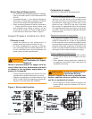
Do Not Use Tefl on Tape
!
!
CAUTION
Wire burner
Burner packaged with appliance
Disconnect electrical power before installing or
servicing the burner.
Provide ground wiring to the burner, metal control
enclosures and accessories. (This may also be
required to aid proper control system operation.)
Perform all wiring in compliance with the Nation-
al Electrical Code ANSI/NFPA 70 (Canada CSA
C22.1)
y
y
y
Electrical shock can cause severe
personal injury or death.
WARNING
!
Electrical Shock Hazard
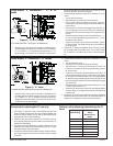
Fuel supply below the level of the burner –
When the fuel supply is more than eight feet below
the level of the burner, a two-pipe fuel supply sys-
tem is required. Depending on the fuel line diam-
eter and horizontal and vertical length, the instal-
lation may also require a two-stage pump. Consult
the fuel unit manufacturer’s literature for lift and
vacuum capability.
Fuel line installation –
Continuous lengths of heavy wall copper tubing
are recommended. Always use fl are fi ttings.
Never use compression fi ttings.
Always install fi ttings in accessible locations.
Proper routing of fuel lines is required to prevent
air cavitation and vibration.
y
y
Fuel line valve and fi lter –
Install two high quality fusible-handle design shut-
off valves in accessible locations on the oil supply
line to comply with the NFPA 31 Standard. Locate
one close to the tank and the other close to the
burner, upstream of the fi lter.
Install a generous capacity fi lter inside the build-
ing between the fuel tank shutoff valve and the
burner, locating both the fi lter and the valve close
to the burner for ease of servicing. Filter should
be rated for 50 microns or less.
y
y
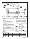
Refer to appliance manufacturer’s wiring diagram
for electrical connections.
Burner installed at jobsite
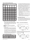
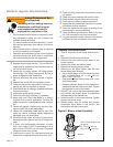
Refer to Figure 7, for typical burner wiring, show-
ing cad cell primary controls. Burner wiring may
vary, depending on primary control actually
used.
The R7184 primary control with valve-on delay
(prepurge) and burner motor-off delay (postpurge),
requires a constant 120 volts AC power source sup-
plied to the BLACK wire on the control. The RED
wire goes to the appliance limit circuit. Please note
that other control manufacturers may use different
wire colors for power and limit connections.
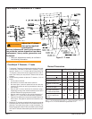
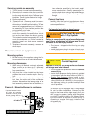
Special wiring required with covered
burners
The mounting plate is not a conduit connec-
tion point. Pass conduit and attached connector
through the opening in the mounting plate and at-
tach it directly to the burner-mounted 4x4 electrical
box.
If attaching a burner cover to a previously installed
burner, attach the mounting plate and then slide the
conduit into the “J” shaped conduit slot.
y
y