Page 2 RWB 6104 BAFG R02
Table of Contents
Hazard Defi nitions and Owner’s Information ........................................................................................3
Information To Be Used Only By Qualifi ed Service Technicians
General Information .........................................................................................................................................3
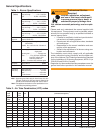
Table 1 Burner Specifi cation ................................................................................................................................4
Table 2 Air Tube Combination (ATC) Codes ………………………………………………………….. .....................4
Notice Special Requirements ..............................................................................................................................5
Inspect/Prepare Installation Site .................................................................................................................5
Chimney or Vent .................................................................................................................................................5
Combustion Air Supply ........................................................................................................................................5
Clearances to burner and appliance ...................................................................................................................6
Combustion chamber - Burner Retrofi tting ..........................................................................................................6
Prepare the Burner ...........................................................................................................................................6
Low Firing Rate Baffl e .........................................................................................................................................6
Burner Fuel Unit ..................................................................................................................................................6
Nozzle and Pump Pressure .................................................................................................................................6
Attach Air Tube ....................................................................................................................................................7
Install Burner Nozzle ...........................................................................................................................................7
Check/Adjust Electrodes .....................................................................................................................................7
Check/Adjust ‘Z’ Dimension - F Heads ................................................................................................................8
Check/Adjust ‘Z’ Dimension - L & V Heads .........................................................................................................9
Servicing nozzle line assembly .........................................................................................................................10
Mount burner on appliance .........................................................................................................................10
Mounting Options ..............................................................................................................................................10
Mounting Dimensions ........................................................................................................................................10
Connect Fuel Lines ...........................................................................................................................................10
Wire Burner ....................................................................................................................................................... 11
Burner Packaged with Appliance ....................................................................................................................... 11
Burner Installed at Job Site ............................................................................................................................... 11
Special Wiring Required with Covered Burners ................................................................................................ 11
Start-up Burner/Set Combustion .............................................................................................................. 13
Set Combustion with Test Instruments ..............................................................................................................13
Perform Regular Maintenance ................................................................................................................... 14
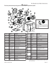
Parts Diagram ...................................................................................................................................................15
Beckett Limited Warranty Information ...................................................................................................16
This manual contains information that applies to both AF and AFG burners. These burners may appear to be basically
identical, but there are differences in design and performance. Please review the comparison chart below:
Feature AF AFG
Static Pressure Capability Conventional - Low range Enhanced - Medium range
Blower Wheel Design Standard strip Special tablock
Inlet Airfl ow Design Standard inlet bell Special airguide
UL Air Tube Combinations “F” Series ONLY “F” or “M” Series
Igniter Gaskets Baseplate/Barrier Optional, as specifi ed Required, always specifi ed
Low Firing Rate Baffl e Not required Required, per specifi cation
NOTICE


