


RWB 6104 BAFG R02 Page 7
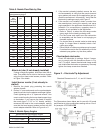
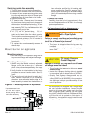
Attach air tube (if not already installed)
If using a fl ange and gasket, slide them onto the air
tube. Then attach the air tube to the burner chassis
using the four sheet metal screws provided. Refer
to Figure 3 for details.
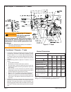
Install burner nozzle (if not already in-
stalled)
Remove the plastic plug protecting the nozzle
adapter threads
Place a ¾” open-end wrench on the nozzle adapter.
Insert the nozzle into the adapter and fi nger tighten.
Finish tightening with a ⅝” open-end wrench. Use
care to avoid bending the burner head support legs
or electrodes. If you remove the head to replace
the nozzle (type “L1”/“L2” or “V1” heads), carefully
reconnect the head to the nozzle adapter, making
sure that the head support makes contact with the
nozzle adapter shoulder. Refer to Figure 4 or 5.
1.
2.
If the nozzle is already installed, remove the noz-
zle line assembly to verify that the nozzle size and
spray pattern are correct for the application (per ap-
pliance manufacturer’s information). Verify that the
electrode tip settings comply with Figure 2.
If the nozzle is not installed, obtain a nozzle from
the manufacturer, having the capacity and spray
angle specifi ed in the appliance manufacturer’s in-
formation. For conversions or upgrades, when in-
formation is not available for the application:
Refer to Table 6 to select the mid-range nozzle
spray angle for the head type being used.
Fire the burner and make sure the combustion
is acceptable and the fl ame is not impinging on
chamber surfaces.
If a shorter fl ame is needed, select a wider spray
angle. If a longer fl ame is needed, select a nar-
rower spray angle.
Either hollow or solid spray patterns may be used.
If combustion results are not satisfactory with the
selected spray pattern, try the other pattern.
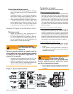
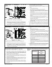
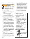
Check/adjust electrodes
Check the electrode tip settings. Adjust if neces-
sary to comply with the dimensions shown in Fig-
ure 2. To adjust, loosen the electrode clamp screw
and slide/rotate electrodes as necessary. Securely
tighten the clamp screw when fi nished.
3.
4.
y
y
y
y
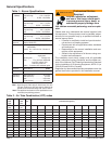
Figure 2. – Electrode Tip Adjustment
Recommended nozzle spray angles
“F” head 70° or 80° nozzle
“L1” & “L2” head 45°, 60°, or 70° nozzle
“V1” head 45°, 60°, or 70° nozzle
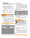
Table 6. Nozzle Spray Angles
Nozzle fl ow rate U. S. gallons per hour of No. 2 fuel oil when
pump pressure (psig) is:
Nozzle
size
(rated at
100 psig)
125
psi
140 psi 150 psi 175 psi 200 psi
0.40 0.45 0.47 0.49 0.53 0.56
0.50 0.56 0.59 0.61 0.66 0.71
0.60 0.67 0.71 0.74 0.79 0.85
0.65 0.73 0.77 0.80 0.86 0.92
0.75 0.84 0.89 0.92 0.99 1.06
0.85 0.95 1.01 1.04 1.13 1.20
0.90 1.01 1.07 1.10 1.19 1.27
1.00 1.12 1.18 1.23 1.32 1.41
1.10 1.23 1.30 1.35 1.46 1.56
1.20 1.34 1.42 1.47 1.59 1.70
1.25 1.39 1.48 1.53 1.65 1.77
1.35 1.51 1.60 1.65 1.79 1.91
1.50 1.68 1.77 1.84 1.98 2.12
1.65 1.84 1.95 2.02 2.18 2.33
1.75 1.96 2.07 2.14 2.32 2.48
2.00 2.24 2.37 2.45 2.65 2.83
2.25 2.52 2.66 2.76 2.98 -
2.50 2.80 2.96 - - -
Table 5. Nozzle Flow Rate by Size
Standard Dimensions for F, L1, and V1 Heads.
The Dimensions shown below are for use with L2 heads
and M series air tube combinations ending with an ‘N’ suf-
fi x (example: AFG70MDAQN)