


Page 4 RWB 6104 BAFG R02
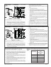
Table 1 – Burner Specifi cations
Capacity
(Note 1)
‘F’ Head (AF & AFG)
Firing rate range: ..............0.40 – 3.00 GPH
Input: ....................... 56,000 – 420,000 Btu
‘L1’ Head (AFG Only)
Firing rate range: ..................0.40 - 1.10 GPH
Input: .....................56,000 – 154,000 Btu/h
‘L2’ Head (AFG Only)
Firing rate range: .................0.50 - 1.00 GPH
Input: ......................70,000 – 140,000 Btu/h
‘V1’ Head (AFG Only)
Firing rate range: .................0.75 - 2.75 GPH
Input: ....................105,000 – 385,000 Btu/h
Certifi cations/
Approvals
UL certifi ed to comply with ANSI/UL296 &
tested to CSA B140.0
Fuels U. S: No.1 or No.2 heating oil only
(ASTM D396)
Canada: No. 1 stove oil or No. 2 furnace oil
only
Electrical Power supply: ...............120 volts AC, 60 Hz,
single phase
Operating load: .......................5.8 Amps max
Motor: ............1/7 hp, 3450 rpm, NEMA 48M
frame PSC rotation CCW
when facing shaft end
Ignition: ... Continuous duty solid-state igniter
Fuel pump
Outlet pressure: ..................................Note 2
Air tube ATC code: ...................................See Table 2
Dimensions
(with cover)
Height (maximum) .......................12.5 inches
Width (maximum) ..........................15 inches
Depth .........................................9.25 inches
Air tube diameter ....................... 4.00 inches
Note 1: Approval agency listed rating for these burners is 0.40 to
3.00 gph. However, the fi ring rate range is limited by the
specifi c air tube combination being used. Refer to Table 2.
Note 2. See appliance manufacturer’s burner specifi cations for rec-
ommended pump discharge pressure.
General Specifi cations
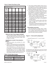
Table 2 – Air Tube Combination (ATC) codes
Firing
Rate
(gph)
Head Static
plate
size
Ven-
turi
ATC Codes for usable air tube lengths
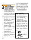
(‘A’ in inches; See Figure 3.)
(min-
max)
(inch-
es)
4-1/2 5 5-3/8 6-5/8 7 7-1/4 9 10-1/2 13 16
0.50-0.75 F0 3-3/8U None AF44XR - AF53XR AF65XR - AF72XR AF90XR AF104XR AF130XR A160XR
0.75-1.25 F3 2-3/4U None AF44XN - AF53XN AF65XN - AF72XN AF90XN AF104XN AF130XN AF160XN
0.85-1.35 F4 2-3/4U None AF44WH - AF53WH AF65WH - AF72WH AF90WH AF104WH AF130WH AF160WH
0.85-1.65 F6 2-3/4U None AF44YB - AF53YB AF65YB - AF72YB AF90YB AF104YB AF130YB AF160YB
1.10-2.00 F12 2-3/4U None AF44XO - AF53XO AF65XO - AF72XO AF90XO AF104XO AF130XO AF160XO
1.65-2.50 F22 2-3/4U None AF44XP - AF53XP AF56XP - AF72XP AF90XP AF104XP AF130XP AF160XP
2.50-3.00 F31 None None AF44XS - AF53XS AF65XS - AF72XS AF90XS AF104XS AF130XS AF160XS
0.50-1.10 L1 3-3/8U 8hole - AFG50MB - - AFG70MB - AFG90MB - - -
0.50-1.00 L2 2-3/4U 8hole AFG50MP - - AFG70MP - AFG90MP - - -
0.75-2.75 V1 2-3/4U 8hole - AFG50MD - - AFG70MD - AFG90MD - - -
0.40-0.75 F0 3-1/2U None AF44WG - AF53WG AF65WG - AF72WG AF90WG AF104WG AF130WG A160WG
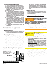
Please read and understand the manual supplied with
this equipment. This equipment must be installed, adjust-
ed and put into operation only by a qualifi ed individual or
service agency that is:
Licensed or certifi ed to install and provide techni-
cal service to oil heating systems.
Experienced with all applicable codes, standards
and ordinances.
Responsible for the correct installation and com-
mission of this equipment.
Skilled in the adjustment of oil burners using com-
bustion test instruments.
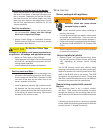
The installation must strictly comply with all applicable
codes, authorities having jurisdiction and the latest revi-
sion of the National Fire Protection Association Standard
for the installation of Oil-burning Equipment, NFPA 31 (or
CSA B139 and B140 in Canada).
Regulation by these authorities take precedence over the
general instructions provided in this installation manual.
y
y
y
y
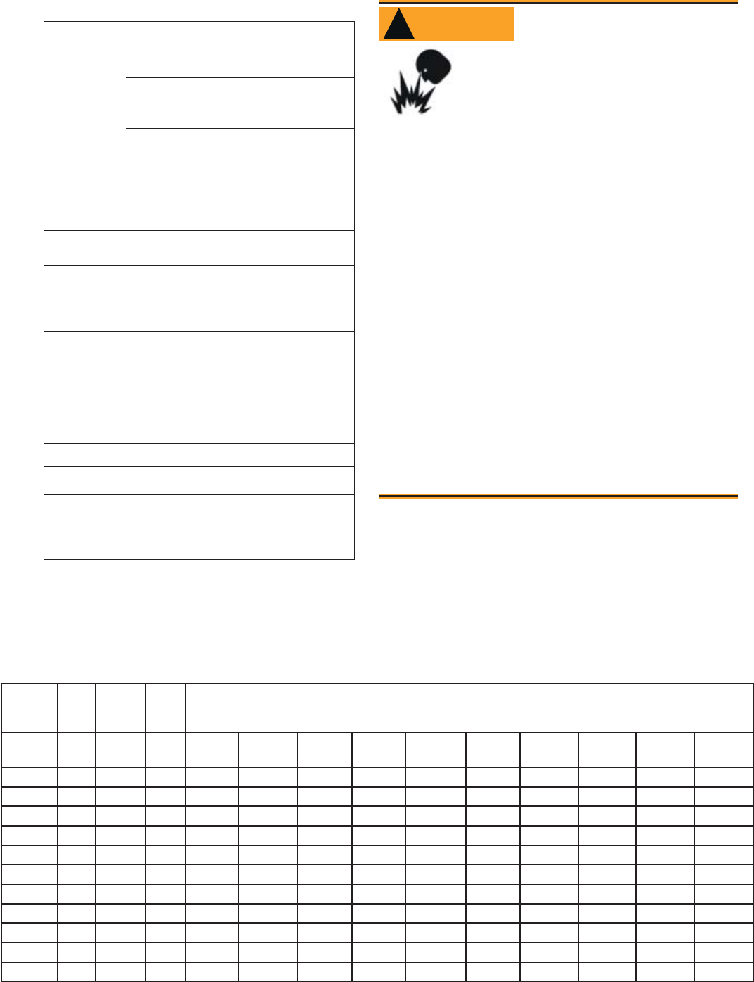
Incorrect installation, adjustment,
and use of this burner could result
in severe personal injury, death, or
substantial property damage from
WARNING
!
Professional Service
Required
fi re, carbon monoxide poisoning, soot or explo-
sion.