


Page 10 RWB 6104 BAFG R02
The burner may be equipped with a single-stage
fuel unit for these installations. Connect the fuel
supply to the burner with a single supply line if you
want a one-pipe system (making sure the bypass
plug is NOT installed in the fuel unit.) Manual bleed-
ing of the fuel unit is required on initial start-up. If
connecting a two-pipe fuel supply, install the fuel
unit bypass plug.
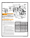
Servicing nozzle line assembly
Turn off power to burner before proceeding.
Disconnect oil connector tube from nozzle line.
Loosen the two screws securing igniter retain-
ing clips and rotate both clips to release igniter
baseplate. Then tilt igniter back on its hinge.
Remove splined nut.
“F” head air tube. - Remove nozzle line assem-
bly from burner, being careful not to damage the
electrodes or insulators while handling. To ease
removal of long assemblies (over 9 inches), ro-
tate assembly 180° from installed position after
pulling partially out of tube.
“L1”, “L2”, and “V1” head air tubes. - S l i d e
nozzle line assembly forward (further into air
tube) so the head clears the venturi opening.
Then rotate the nozzle line assembly 90° so the
nozzle line end points up. Pull the nozzle line
assembly toward you and remove assembly
from burner.
To replace the nozzle assembly, reverse the
above steps.
Mount burner on appliance
Mounting options
Bolt the burner to the appliance using the fac-
tory-mounted fl ange or an adjustable fl ange.
Mounting dimensions
When using the Beckett universal adjustable
fl ange, mount the air tube at a 2° downward
pitch unless otherwise specifi ed by the appli-
ance manufacturer.
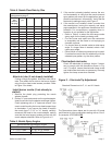
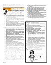
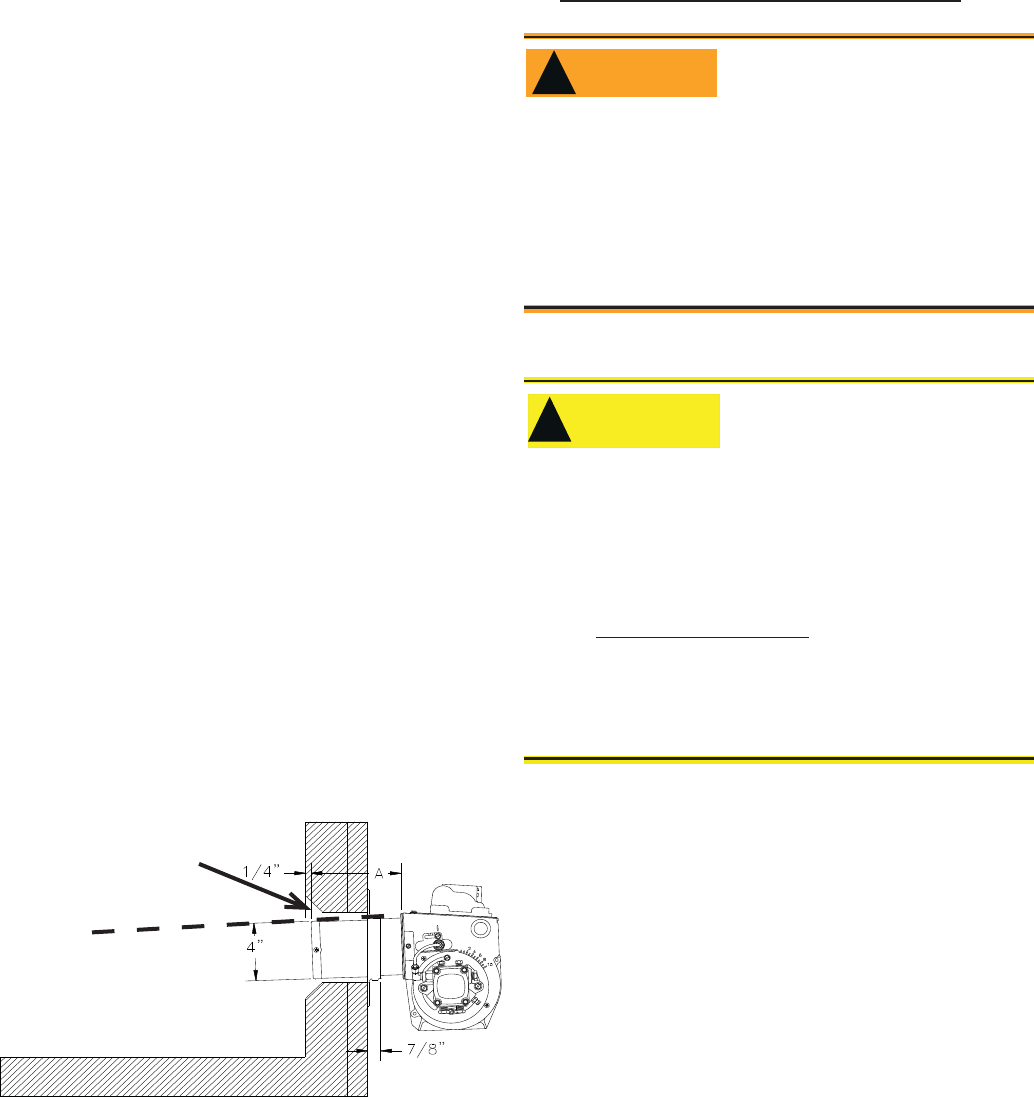
Verify that the air tube installed on the burner
provides the correct insertion depth. See Fig-
ure 6.
The end of the air tube should normally be ¼”
back from the inside wall of the combustion
chamber. Never allow the leading edge of the
head assembly to extend into the chamber, un-
1.
2.
3.
4.
5.
6.
7.
1.
1.
2.
3.
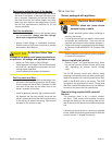
The burner is shipped without the by-pass plug
installed.
Install the by-pass plug in two-pipe oil supply sys-
tems ONLY.
y
y
Failure to comply could cause Immediate pump
seal failure, pressurized oil leakage and the po-
tential for a fi re and injury hazard.
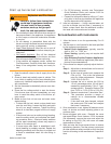
WARNING
!
Do Not Install By-pass Plug
with 1-Pipe System
less otherwise specifi ed by the heating appli-
ance manufacturer. Carefully measure the in-
sertion depth when using an adjustable fl ange.
Verify the insertion depth when using a welded
fl ange.
Connect fuel lines
Carefully follow the fuel unit manufacturer’s litera-
ture and the latest edition of NFPA 31 for oil supply
system specifi cations.
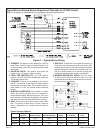
Fuel supply level with or above burner –
SK8745
Figure 6. – Mounting Burner in Appliance
Tilt down 2
o
If space between burner
air tube and opening
exceeds 1/2 inch, pack
burner opening with ce-
ramic fiber refractory.
The oil supply inlet pressure to the burner cannot
exceed 3 psig.
Insure that a pressure limiting device is installed
in accordance with the latest edition of NFPA 31.
Gravity Feed Systems: Always install an anit-
siphon valve in the oil supply line or a solenoid
valve (RWB Part # 2182602U) in the pump/noz-
zle discharge tubing to provide backup oil fl ow
cut-off protection.
y
y
y
Damage to the fi lter or pump seals could cause
oil leakage and a fi re hazard.
Oil Supply Pressure
Control Required
!
!
CAUTION