


Page 6 RWB 6104 BAFG R02
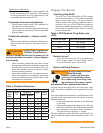
Table 4. AFG Reduced Firing Rates (with
LFRB)
Burner head type Low Firing Rate Baffl e installed
F0 up to 0.65 gph
F3 or L1 up to 0.85 gph
F4 or F6 up to 0.90 gph
V1 up to 1.00 gph
Prepare the Burner
Low Firing Rate Baffl e
The AFG Low Firing Rate Baffl e (LFRB) reduces
the air fl ow and pressure. The LFRB is sometimes
used for fi ring rates under 1.00 gph as listed in
Table 4. Refer to the appliance manufacturer’s in-
structions. Do not omit the LFRB when specifi ed.
Omitting the baffl e when specifi ed or installing the
baffl e when not specifi ed could result in impaired
burner performance.
Burner fuel unit
Verify that the burner fuel unit is compatible with
the oil supply system. For more details, refer to
“Connect fuel lines” later in this manual.
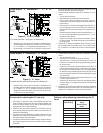
y
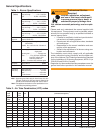
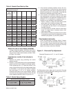
Chamber Dimensions (inches)
Firing
Rate
(GPH)
Round
I.D.
Rectangular Height Floor to
nozzle
Width Length
0.50 8 7 8 12 5-6
0.75 9 8 9 12 5-6
1.00 10 9 10 12.5 5-6
1.25 11 10 11 12.5 5-6
1.50 12 11 12 13 6-7
2.00 14 12 15 13.5 6-7
2.50 16 13 17 14 7-8
3.00 18 14 18 15 7-8
Table 3. Chamber Dimensions
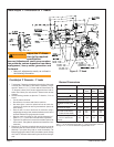
Outside air kit applications
Refer to separate instruction sheet supplied with
AF/AFG outside air kit for installation. This optional
kit allows combustion air to be piped directly to the
burner (Beckett part number 51747).
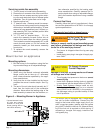
Clearances to burner and appliance
Provide space around burner and appliance for
easy service and maintenance.
Check minimum clearances against those shown
by the appliance manufacturer and by applicable
building codes.
Combustion chamber — Burner retrofi t-
ting
Verify that the appliance combustion chamber pro-
vides at least the minimum dimensions given in
Table 3.
y
y
When retrofi tting appliances that have unlined
stainless steel combustion chambers, protect the
chamber by lining the inside surfaces with a ce-
ramic fi ber blanket, such as a wet-pac or other
suitable refractory material.
Some steel chambers may not require liners be-
cause the appliance was designed and tested
for use with fl ame retention burners. Refer to the
manufacturer’s instructions.
y
y
Failure to comply could result in damage to the
heating equipment and result in fi re or asphyxi-
ation hazards.
WARNING
!
Protect Steel Combustion
Chamber From Burnout
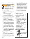
Use only nozzles having the brand, fl ow rate (gph), spray
angle and pattern specifi ed by the appliance manufac-
turer.
Follow the appliance manufacturer’s specifi cations for the
required pump outlet pressure for the nozzle, since this
affects the fl ow rate.
Nozzle manufacturers calibrate nozzle fl ow rates
at 100 psig.
When pump pressures are higher than 100 psig,
the actual nozzle fl ow rate will be greater than the
gph stamped on the nozzle body. (Example: A
1.00 gph nozzle at 140 psig = 1.18 gph)
Securely tighten the nozzle (90 torque inch pounds). For
typical nozzle fl ow rates at various pressures refer to Ta-
ble 5.
y
y
Incorrect nozzles and fl ow rates
could result in impaired combus-
tion, under-fi ring, over-fi ring, soot-
ing, puff-back of hot gases, smoke
WARNING
!
Correct Nozzle and Flow
Rate Required
and potential fi re or asphyxiation hazards.
Nozzle and Pump Pressure