


Manual 2100-422M
Page 35 of 42
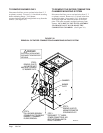
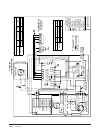
COMBINATION COMBUSTION
CHAMBER/BURNER MOUNTING
SYSTEM
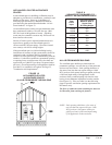
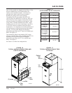
The furnace has been designed with a combustion
chamber mounting system that enables service
personnel to remove the combustion chamber, its
mounting system, and burner assembly as one unit for
inspection and/or service on the bench. It has also been
designed to remove the burner assembly independently
from the mounting system to perform basic annual
service and inspection. The mounting system is
completely adjustable so exact alignment between the
burner tube and combustion chamber may be assured
prior to installation into the furnace. See Figure 19
and 20.
WARNING
The procedures described in Figures 19 and
20 should be conducted only by a qualified
service technician.
Improper servicing could cause electric shock
hazard, fires or explosion resulting in
damage, injury or death.
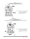
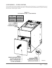
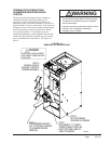
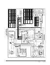
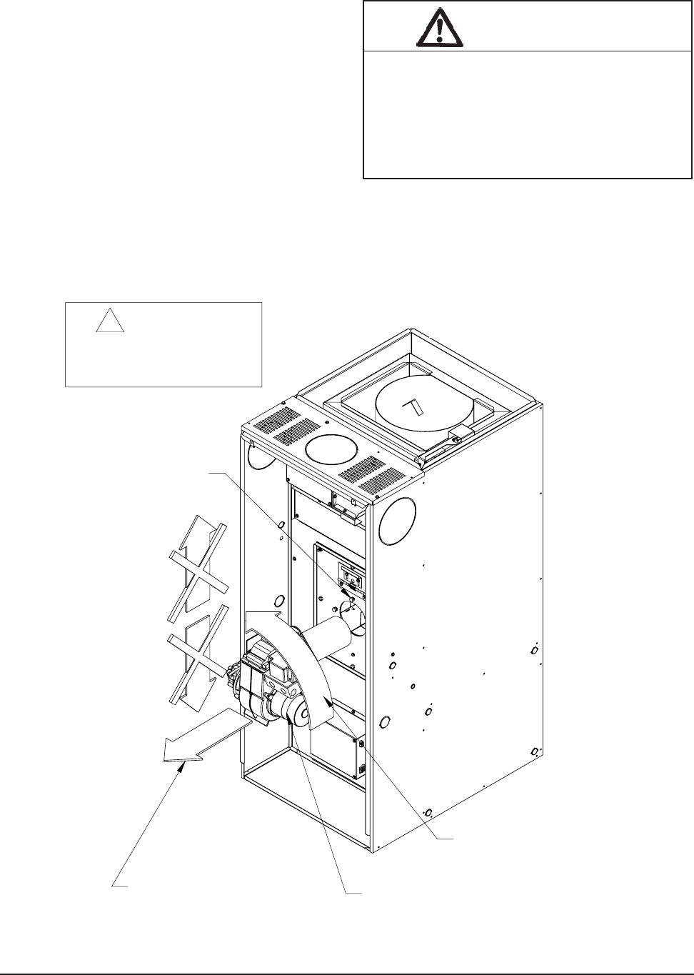
BURNER REMOVAL
INSTRUCTIONS
STEP 1:
DISCONNECT "T-T" WIRES,
POWER CONNECTIONS, AIR
BOOT (OPTIONAL) AND OIL
LINES TO BURNER.
STEP 2:
LOOSEN (3) BOLTS
ENOUGH TO ROTATE
BURNER ASSEMBLY.
STEP 3:
ROTATE BURNER
COUNTER-CLOCKWISE
STEP 4:
PULL BURNER STRAIGHT
OUT TO PREVENT DAMAGE
TO CHAMBER DURING
REMOVAL.
MIS-1834
*ELECTRICAL SHOCK HAZARD
*DISCONNECT POWER BEFORE
SERVICING.
DANGER
!
FIGURE 19
REMOVAL OF BURNER ONLY