


Manual 2100-422M
Page 20 of 42
1. PREPARATION STEPS
A. Calibrate and Check Operation of
Measuring Equipment Follow
manufacturer’s recommended procedures for
calibration and equipment check out.
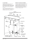
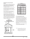
B. Prepare Heating Unit for Testing Drill two
1/4 inch holes in the flue between the heating
plant and the barometric draft regulator. If
space permits, the holes should be located in a
straight section of the flue, at least two flue
diameters from the elbow in the flue pipe and
at least one diameter from the draft regulator.
The purpose of the two holes in the flue pipe is
to speed up testing and reduce instrument
handling.
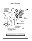
C. Clean and Seal Heating Plant Make sure the
burner blast tube, fan housing, and blower
wheel are clear of dirt and lint. Seal any air
leaks into the combustion chamber.
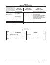
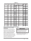
D. Nozzle Inspection Annual replacement of
nozzle is recommended. The nozzle size
should match the design load. DO NOT
OVERSIZE. (Determination of oversizing can
be determined prior to your adjustment. If the
firing rate should be reduced refer to Table 4.)
Short cycles and low percent “on” time result
in higher overall pollutant emissions and lower
thermal efficiency. An in-line oil filter will
reduce service problems due to nozzle
clogging.
The filter should be located as close as possible
to the oil burner. Care should be taken to
prevent air leakage in the oil suction line. Use
continuous runs of copper tubing and use
minimum number of joints and fittings.
Always use flare fittings.
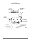
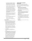
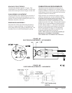
E. Adjustment of Electrodes Adjust ignition
electrodes as specified in Figure 10.
F. Operate Burner Operate burner, adjust air
setting for good flame by visual observation,
and run for at least 10 minutes or until
operation has stabilized.
G. Check Burner Pressure Bleed air from
pump and nozzle piping. Check pump
pressure and adjust to nameplate pump
pressure, if necessary.
2. COMBUSTION ADJUSTMENT STEPS
H. Set Draft Check the draft reading over the
fire with a draft gauge through a hole in the
inspection door. The hole is above the flame
level. Adjust the barometric draft regulator on
the flue to give the over fire of -.02" W.C.
I. Check Smoke Readings After burner has
been operating 5 or 10 minutes, take a smoke
measurement in the flue, following the smoke
tester instructions. Oily or yellow smoke spots
on the filter paper are usually a sign of
unburned fuel, indicating very poor combustion
(and likely high emissions of carbon monoxide
and unburned hydrocarbons). This condition
can sometimes be caused by too much air, or by
other factors. If this condition cannot be
corrected, major renovation or even burner
replacement may be necessary.
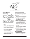
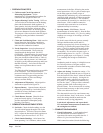
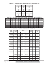
J. Develop Smoke - CO2 Curve Record
measurements of smoke and CO
2
from the flue.
Then establish the smoke - CO
2
curve by taking
readings over a range of air settings, as shown
in Figure 8.
To do this, start with the air gate set at nearly
full open and then take smoke and CO
2
readings at progressively lower air settings, as
necessary to visualize the general shape of the
curve. (The CO
2
readings will increase as the
air setting is decreased, unless combustion is
incomplete.) Do not set the air gate to give a
smoke reading above No. 4 or No. 5. Plot the
points on graph paper, as in Figure 8. Usually
3 or 4 readings are enough to establish the
curve.
In adjusting each air setting, it is helpful to note
the various positions of air gate at which
measurements are made so that the final setting
can be located quickly.
K. Adjust Air Setting Examine the smoke - CO
2
plot and, keeping in mind the curve of Figure 6,
note the location of the “knee” where the smoke
number begins to rise sharply. Noting the air
gate position marks, adjust the air setting to a
CO
2
level 1/2 to 1 percent lower than the CO
2
level at the “knee”. (This provides a tolerance
against possible shifts in the setting over a
period of time.) Do not increase the air setting
any more than necessary on the lower portion
of the curve below the “knee”.
The characteristic curve for some burners may
not yield a distinct “knee” in the curve. In such
cases, the setting should be made near the
minimum smoke, (using judgement).
Lock the air adjustment and repeat draft,
CO
2
and smoke measurements to make sure
the setting has not shifted.
3. COMBUSTION DIAGNOSIS
L. Check Performance A well-matched and
well-tuned burner should be capable of
operation with smoke not greater than No. 2
and at a CO
2
level not less than 10%.
If this cannot be reached, check the following: