


Manual 2100-422M
Page 2 of 42
CONTENTS
Getting Other Information and Publications ........ 3
Installation and Operating Instructions
Equipment Selection ............................................. 4
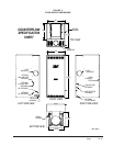
Locating the Furnace ............................................ 4
Installing the Furnace ........................................... 8
Duct Work ............................................................. 8
Installing a Cooling Unit ........................................ 8
Wiring .............................................................. 9
Oil Line Piping..................................................... 12
Beckett AFG Oil Burner .............................. 12 & 13
Beckett “CleanCut” Oil Pump .............................. 13
Beckett Solid State Igniter................................... 13
Beckett R7184B Primary Control ........................ 13
Beckett R7184B Primary Operational Guide ...... 14
Beckett GeniSys 7505 ................................ 14 – 17
Burner States, Reset Button Op., Priming the Pump, Cad
Cell Resistance Indicator, Reset Restricted Lockout
Burner Set up and Adjustments ............ 19, 20 & 21
Short Form Adjustment Procedure ..................... 21
Combustion Air Requirements ............................ 25
Louvers and Grilles ............................................. 30
Venting Options .................................................. 30
Thermostat.......................................................... 30
TABLES
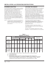
Table 1 Minimum Clearances ............................. 4
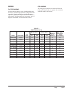
Table 2 Dimensions FLF/R Models ................... 5
Table 3 Electrical Data........................................ 9
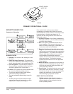
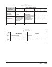
Table A Reset Button Operation ....................... 15
Table B Status Lights ........................................ 15
Table 4 Furnace Data ....................................... 19
Table 5 Correlation of % of CO
2
, O
2
and
Reserve Air .......................................... 24
Table 6 No. 2 Fuel Oil Efficiency Chart ............. 24
Table 7 Recommended Start-Up Settings ........ 24
Table 8 Sq.Ft. Required as
Unconfined Space ............................... 27
Table 9 Minimum Ventilation Openings ............ 28
Table 10 Temperature Rise Ranges, Limit
Control Settings, and
Heating Blower Speeds ....................... 31
Table 11 Filter Sizes for Oil Furnaces ................ 32
CHARTS
Chart 1 FH085D36F Data................................. 38
Chart 2 FH110D48F Data ................................. 38
Chart 3 FH110D60F Data ................................. 38
Chart 4 FLF/FLR085D36F Data ....................... 38
Chart 5 FLF/FLR110D48F Data ....................... 38
Chart 6 FLF/FLR110D60F Data ....................... 38
Chart 7 FLR140D60F Data............................... 39
Chart 8 FC085D36F Data................................. 39
FIGURES
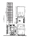
Figure 1 FLF/R Models Dimensions ................ 5
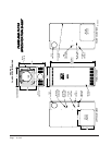
Figure 2 FH Models Dimensions ..................... 6
Figure 3 FC Models Dimensions ..................... 7
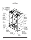
Figure 4 Typical Unit Setup - FLF.................. 10
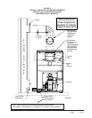
Figure 5 Typical Flue Installation
Requirements - FLF ........................ 11
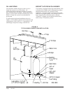
Figure 6 Typical Single Inside
Tank Installation............................... 12
Figure 7 Electronic Blower Control ................ 18
Figure 8 Typical Smoke-CO
2
Characteristic .. 22
Figure 9 Pressure Gauge Connection to
Bleed Port ....................................... 23
Figure 10 Electrode Adjustments..................... 25
Figure 11 Combustion Air Boot Assembly ....... 26
Figure 12 All Air From Inside Building ............. 27
Figure 13 All Air From Outdoors ...................... 28
Figure 14 All Air From Outdoors Through
Ventilated Attic................................. 29
Figure 15 All Air From Outdoors - Inlet Air
From Ventilated Crawl Space and
Outlet Air to Ventilated Attic ............. 29
Figure 16 Typical Installation of FR26 and FR27.
Filter Rack ....................................... 32
Figure 17 Typical Installation of FR25 Filter
Kit .................................................... 32
Figure 18 Filter Installation - Lo-Boy Models ... 33
Figure 19 Removal of Burner Only .................. 35
Figure 20 Removal of Entire Combustion
Chamber Mounting System ............. 36
Filters
Lo-Boy Models – Filter Locations...................... 33
Maintenance
Lubrication .......................................................... 34
Inspect Air Filter .................................................. 34
Final Inspection and Test .................................... 34
Service Hints....................................................... 34
Combination Combustion Chamber/Burner
Mounting System ................................................ 35
To Remove Burner Only ..................................... 36
To Remove Entire Combustion Chamber
Mounting System ................................................ 36
Common Causes of Trouble ............................... 37
Care of Finish ..................................................... 37
Cleaning of the Heat Exchanger ......................... 37
Blower System Resistance Charts................. 38-39
Wiring Diagrams ............................................ 40-42