


Manual 2100-422M
Page 21 of 42
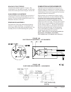
1. Air leaks into the combustion chamber or
heat exchanger can dilute the combustion
gases and prevent normal CO
2
readings.
Such leaks should be sealed with furnace
cement or other high-temperature sealant.
To check for dilution by leakage, measure
the CO
2
at as high a point as possible over
the fire, using a stainless steel tube
inserted through the fire door sample hole
(as described earlier for overfire draft
measurements), and compare this with the
CO
2
measured in the flue. A difference of
more than 1 percent CO
2
between the flue
and overfire reading usually indicates air
entry through leaks that have not been
properly sealed.
Seal between the probe and inspection door
sample hole during test. The inspection
door hole should be sealed when not being
used to avoid leakage of air through it.
(See Step H.)
2. If the CO
2
level of 10% cannot be reached
without exceeding No. 2 smoke, poor
mixing of air and fuel is likely.
It may be necessary to replace the
combustion head or try different settings.
4. FINAL CHECKS
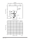
M. Measure Stack Temperature Operating the
unit at an excessive firing rate will generate
more heat than the heat exchanger can utilize
and result in unnecessary heat loss up the
chimney. Other causes of excessive heat loss
are badlysooted heat exchanger surfaces and
excessive draft. The temperature of the flue gas
provides an indication of these heat losses.
Measure flue temperature by subtracting the
room air temperature from the thermometer
reading. Excessive stack loss is indicated if the
net stack temperature during steady operation
exceeds 600° F.
N. Check Ignition Check operation over
repeated cycles to insure prompt ignition on
starting.
O. Check Pump Cutoff Slow pump cutoff at the
end of a firing cycle can cause smoke and other
pollutant emissions. Check for prompt pump
cutoff by observing flame or by testing smoke
at shutdown. If poor cutoff is observed, make
sure air is purged from the pump and nozzle
line. Air trapped in the pump or nozzle line
will expand when heated, thus causing oil to
drip into the combustion chamber after
shutdown. If poor cutoff persists, repair or
replace pump. Also make sure the pump
solenoid is working - if not replace.
SHORT FORM ADJUSTMENT
PROCEDURE
Some burner service organizations may wish to
perform a shorter procedure for the adjustment of oil
burners. The following is an example of such a short
form prepared by the National Association of Oil Heat
Service Managers.
1. SERVICE AND CLEAN BURNER
Follow company procedure to complete the
cleaning and servicing. Operate burner for ten
minutes while tools are gathered and are cleaned.
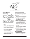
2. CHECK DRAFT
Set draft regulator, if necessary. Regulator should
be adjusted to achieve a -.02" W.C. over fire
condition. The more restricted and lengthy the
flue, the higher the draft necessary to obtain the
accepted over fire conditions.
3. SMOKE TEST
Follow the instructions of the manufacturer of the
smoke tester and take a smoke sample. Adjust the
air to obtain a preliminary reading of about No. 3
spot. Then readjust the air to obtain the lowest
possible reading, but do not open the air adjustment
more than absolutely necessary to obtain a trace or
No. 0 spot.
4. CO
2
TEST
Check CO
2
levels. This level should be between
10% and 12%.