38 Optional Equipment (for qualified installers only)
Travis Industries 93508115 4050113
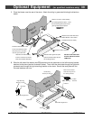
6 Make the gas line connection, bleed the gas line (if applicable), start the heater and thoroughly leak-
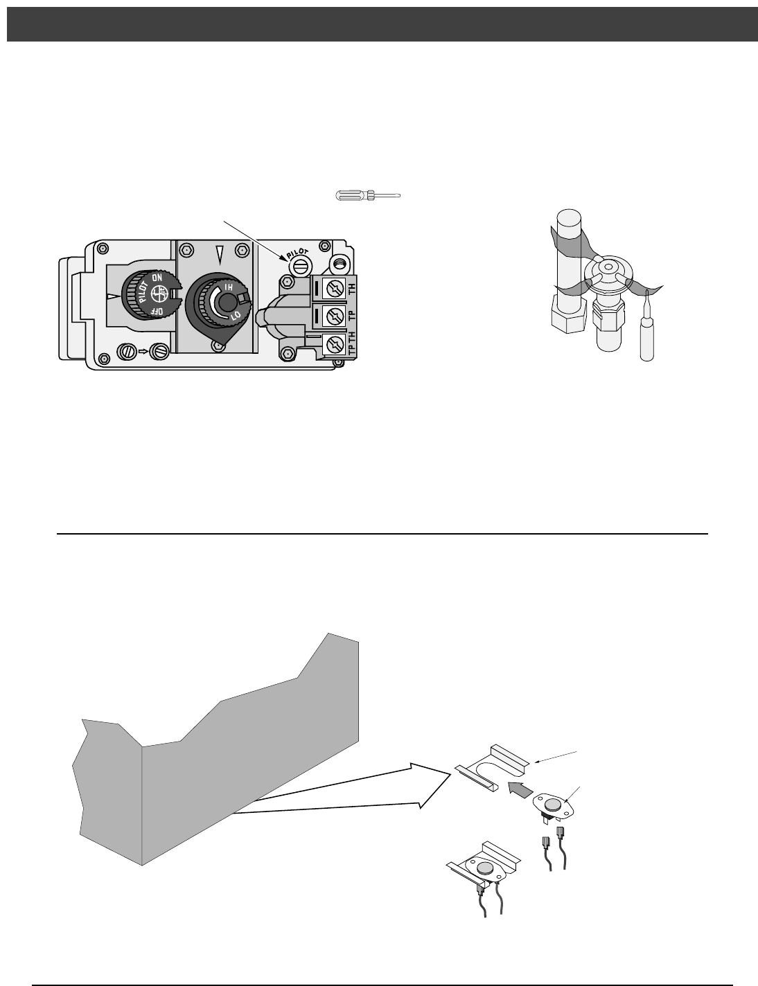
test all gas connections and the gas control valve. Check the pilot. Adjust if necessary.
WARNING: When lighting or re-lighting the pilot, the glass must be removed (see
page 22).
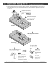
Standard
Screwdriver
The pilot flame must contact the thermocouple and
thermopile (see the illustration below). Adjust the pilot up or
down as necessary.
To adjust the pilot flame, turn this screw (NOTE: if totally
unscrewed gas will come out of this port). Clockwise
lowers the flame while counter-clockwise raises it.
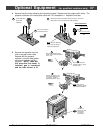
7 Install the log set (see page 24).
8 Replace the glass (see page 22).
Blower (part # 99000153)
WARNING: Turn the gas control valve to off and make sure the appliance has fully cooled prior to
conducting service.
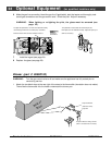
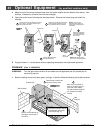
1 Attach the two black wires at the rear right of the stove to the thermodisk (orientation does not matter).
Then slide the thermodisk into the holder underneath the burner pan.
Snap Disk Bracket
(attached to stove)
Snap Disk
Snap Disk Wires on Wiring Harness
(Black - orientation does not matter)
Back of
Stove


