


PAGE 6 INSTALLATION (continued)
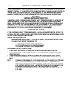
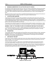
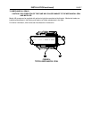
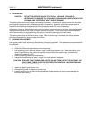
FIGURE 3
COUPLING ALIGNMENT
FINAL COUPLING ALIGNMENT (continued)
B. Check the angular alignment with a micrometer or caliper. Measure from the outside of one flange to
the outside of the other at intervals around the periphery of the coupling. Determine the maximum
and minimum dimensions. DO NOT ROTATE THE COUPLING. The difference between the
maximum and minimum dimensions should not exceed manufacturer’s recommendations. If a
correction is required, you must always recheck the parallel alignment.
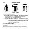
C. If the coupling employs a two-piece sleeve with a wire ring, force the ring into its groove in the center
of the sleeve. It may be necessary to pry the ring into position with a blunt screwdriver.
WARNING: CHECK SAFETY CODES, AND ALWAYS INSTALL PROTECTIVE GUARD OR
SHIELD AS REQUIRED BY VARIOUS FEDERAL, STATE AND LOCAL LAWS AND
REGULATIONS CONCERNING OSHA.
WARNING: COUPLING SLEEVES MAY BE THROWN FROM THE ASSEMBLY WHEN
SUBJECTED TO A SEVERE SHOCK LOAD.
11. FLEXIBLE SHAFTING ALIGNMENT
For installation and alignment of intermediate flexible shafting, refer to the manufacturer’s instructions.
12. ROTATION
Before connecting the coupling halves, bump start the driver to verify rotation is in the proper direction. The
correct pump rotation is indicated by a directional arrow on the pump casing.