


PAGE 16 MAINTENANCE (continued)
7. PUMP ASSEMBLY (continued)
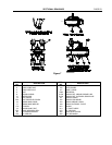
CAUTION: THIS PUMP MAY BE SUPPLIED IN SEVERAL DIFFERENT CONFIGURATIONS.
EACH USES DIFFERENT BEARING COVERS AND HOUSINGS WITH DIFFERENT
DRAWING REFERENCE NUMBERS. DESPITE THE FOLLOWING INSTRUCTIONS,
ALWAYS REFER TO THE SECTIONAL DRAWINGS CONTAINED IN THIS MANUAL
BEFORE PROCEEDING, TO INSURE THAT YOU HAVE INSTALLED ALL REQUIRED
LIP SEALS, O-RINGS, ETC.
D. Install the shaft sleeves (14), shaft sleeve nuts (213) and O-rings (452), if your pump uses them, on the
shaft. The shaft sleeves will be secured by one of three methods and you should proceed as follows:
Sleeves Secured With Loctite And Sleeve Nuts: Apply two beads of Loctite No. 601 around the shaft on the
shaft/shaft sleeve fit, one approximately 2 inches from the impeller hub and the second at the threaded end.
Slide the shaft sleeves part way onto the shaft and rotate them at least one full revolution to evenly spread the
Loctite, then slide the sleeves over the shaft until they butt firmly against the impeller hub. Install and tighten
the shaft sleeve nuts (213) and the setscrews.
Sleeves Secured With Loctite Only: Clean the shaft, the bore of the sleeves and the bore of the
impeller with Loctite “Safety Solvent #75559.
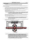
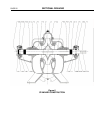
Install the impeller key in the shaft and coat the impeller area on the shaft with Loctite 601. Press the
impeller onto the shaft, centering it between the shoulders as shown in Figure 5.
Coat the shaft on the shaft/sleeve fit and the bore of the sleeves with Loctite 601. Slide the sleeves
part way onto the shaft and rotate them at least one full revolution to evenly spread the Loctite, then
slide the sleeves over the shaft until they butt firmly against the impeller hub. Check the sleeve location
again and let the Loctite cure for 8 hours before completing the pump assembly.
Sleeves Installed With O-rings: Slide the shaft sleeves over the shaft until they engage the key and
butt firmly against the impeller hub. Install the O-rings in the outboard shaft sleeve nut end of the
sleeve and tighten the shaft sleeve nuts and setscrews.
E. If your pump is equipped with mechanical seals or solid packing glands, install the seals (456) and
mechanical seal glands (B31) or solid packing glands before proceeding. Refer to the seal
manufacturer’s instructions for installation.
F. Install the water slingers (126) on each end of the shaft.
G. Install the outboard and inboard bearing covers (159) on the shaft.
WARNING: TO PREVENT POSSIBLE SERIOUS PERSONAL INJURY AND DAMAGE TO THE
BEARINGS, PRESSURE SHOULD BE APPLIED TO THE INNER BEARING RACE
ONLY.
H. Install the outboard / thrust (168) and inboard / radial bearings (163).
Note: The pump is designed to have a .000 to .001 interference fit between the bearings and
the shaft.
I. Install the bearing lock washer (162) and bearing locknut (161) on the outboard end of the shaft.
Pack both bearings approximately one-half full of polyurea base all-purpose bearing grease.
J. Install bearing cartridges (A158 and B158 if grease lubricated, or C158 and D158 if oil lubricated or
E158 and F158 if water lubricated) over the bearings and securely bolt the bearing covers to the
bearing housings using the appropriate capscrews.
WARNING: BE CAREFUL WHEN POSITIONING THE ROPES TO AVOID THE ROTOR SLIPPING
AND CAUSING POSSIBLE SERIOUS PERSONAL INJURY.
CAUTION: WHEN LOWERING THE ROTOR, BE CAREFUL TO PROPERLY POSITION THE
WEARING RINGS. FAILURE TO DO SO COULD SERIOUSLY DAMAGE THE RINGS.
K. Using a double rope sling, carefully lower the rotor assembly into the lower casing (2).